This thread has been locked.

If you have a related question, please click the "Ask a related question" button in the top right corner. The newly created question will be automatically linked to this question.

MC33063A: Correct functionning of MC33063A

Part Number: MC33063A

Hello,

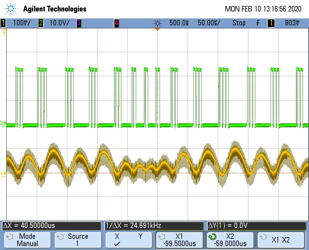
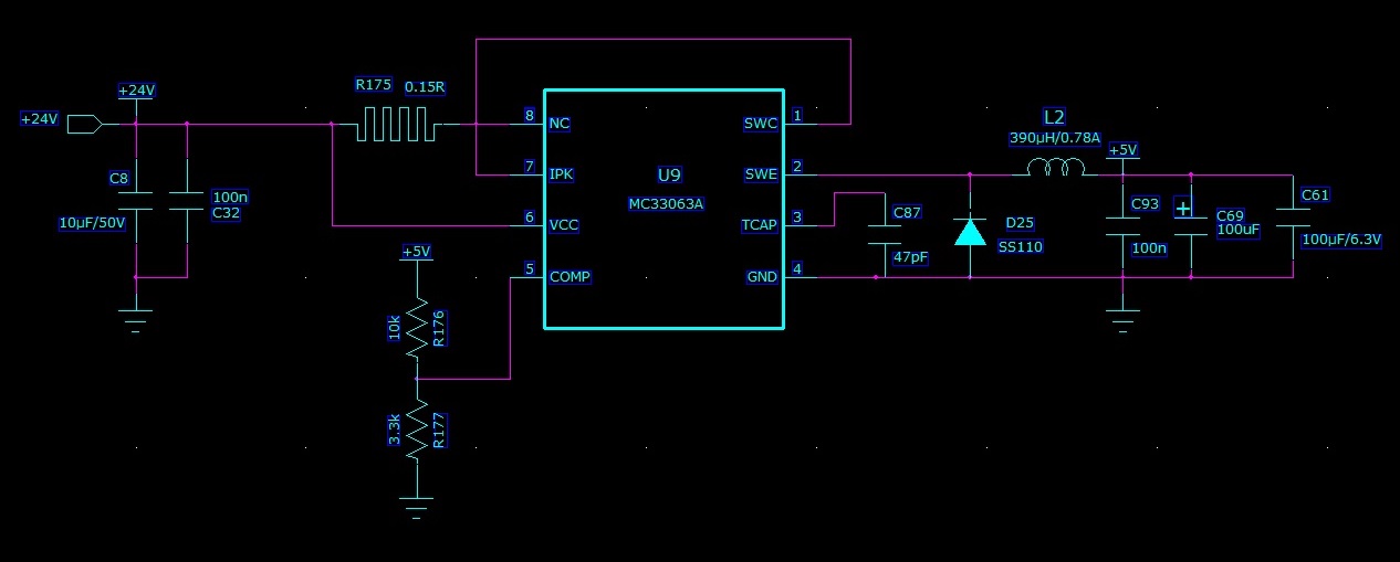
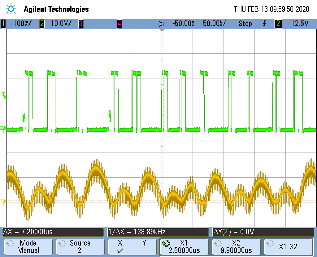
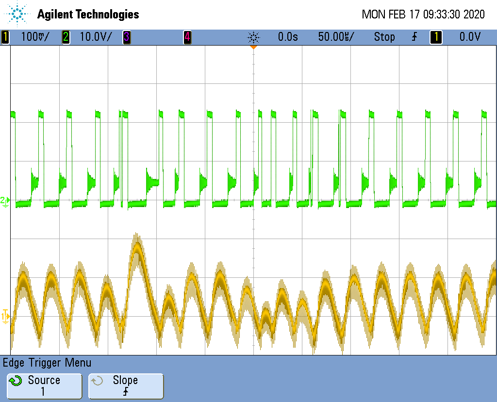
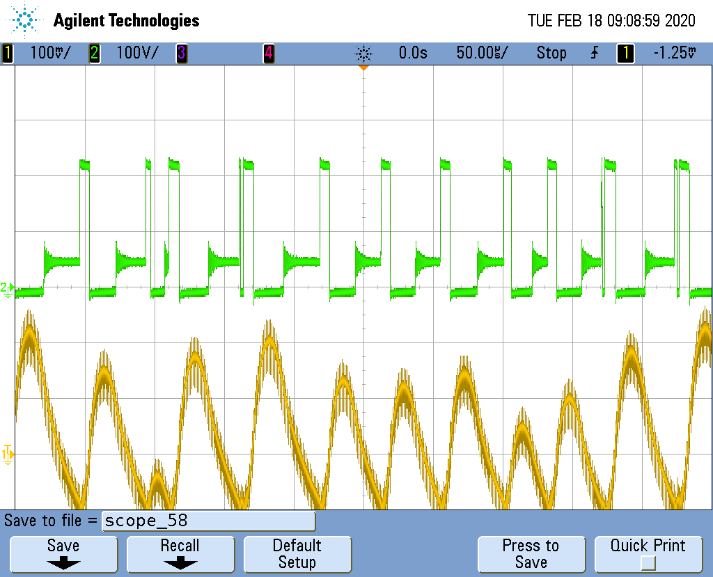
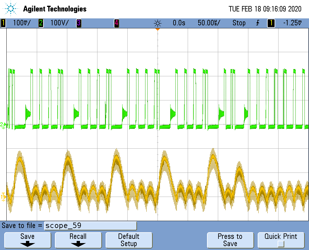
I would like to know if the functionning described below is correct for an MC33063A. I am refering to the signal at pin #2 of the MC33063A in green colour which has a max frequency of the pulses of 200 KHz. In yellow colour, the signal is the AC component of the output of the MC33063A. Schematic of the test is described below. The MC33063A regulates at +5V DC from a +24V input. Current output is about 300 mA. The CT value is quite low but I obtain lowest ondulations on the output with this capacitor of 47 pF. I am wondering if I am oustide spec with this 47pF capacitor. When the capacitor is above 47 pF, ondulations on the output are well above 100 mV which is not good for our application.

Thank you in advance for your comments.

Best regards,

Fabrice

  • Hi User,

    Thank you for using MC33063.  The datasheet says the oscillator frequency is up to 100kHz, while your circuit enters 200kHz, which is a bit higher than datasheet recommended.  CT should be increased. 

    Calculated backward:  24Vin and 5Vout requires a duty cycle of about 0.23 (taking into account the diode drop effect on Vout regulation).  At 100kHz, you need Ton =2.3us, leading to CT= 4.5x 10^(-5) x 2.3us = 92pF, then the min capacitor that you should choose is about 100pF to remain 100kHz.

    The main issue is that your circuit does not work stably. According to the App Note https://www.ti.com/lit/an/slva252b/slva252b.pdf, the min current limit resistor is 0.2 Ohm, while you used 0.15 Ohm.  Would you you please please increase R175 and see the switching is more repetitive regular than more random?

    Thanks,

    Youhao Xi, Applications Engineering

  • Hello Youhao Xi,

    Thanks for your quick reply. I did some test with the provided suggestions and here are the results.

    Suggestions:

    • CT=100pF
    • Resistor of more than 0.2 ohm => Ripk=0.3 ohm
    1. First test with CT=47pF and Ripk=0.15ohm

    2. Second test with CT=100pF and Ripk=0.30ohm

    I cannot see any clear improvements in between the two tests. With a 100pF capacitor, oscillator frequency are still about 140 KHz so above spécifications. I cannot understand how this is possible if the calculated CT value is 92pF at 100 KHz.

    Thank you in advance for your comments.

    Best regards,

    Fabrice

  • Hi Fabrice,

    The effective capacitance may be smaller than the surface value due to the voltage coefficient of the ceramic capacitors.  Can you increase to 200pF? From your test waveforms, if there is single pulse each time, the ripple voltage will be smaller.  Now you have two consecutive or three consecutive pulses.  I would also increase the sense resistor to make sure each time the current is limited in each pulse, then there is no extra charge for each switching cycle.  

    Let see if there is any improvement.

    Thanks,

    Youhao

  • Hello Youhao,

    Thanks for your suggestions.

    I updated Ct for a value of 220 pF. Please, find below the waveform found:

    First test with CT=100pF and Ripk=0.3ohm

    Second test with CT=220 pF and Ripk=0.3ohm

    You can see that with 220 pF, the fluctuations of the output voltage are higher. The lower CT has been, the lower the fluctuations.

    I used a Ripk of 0.3 ohm without better success.

    Thank you in advance for your answer.

    Best regards,

    Fabrice

  • Hi Fabrice,

    Sorry for not getting a better results, but I am a little confused. With C=100pF and Ripk=0.3 Ohm, the results on Feb 17th look quite different from Feb 13th. On 17th you have fewer double pulses.  Is the load at a different level?

    My intention is to get to repetitive single pulses which would reduce the ripple voltage.  May I ask you to try to change back to C=47pF and increase the Ripk to 0.3Ohm, or even 0.5Ohm, and see if you get a better result?

    Thanks,

    Youhao

  • Hi Jouhao,

    Thanks for your reply. I confirm that the load has not changed during measurements (but the inductor; pleqse reqd below).I have changed back from CT=220 pF and Ripk=0.3ohm to CT=47 pF and Ripk=0.3ohm. Below are the results:

    First test with CT=220pF and Ripk=0.3ohm

    Second test with CT=47pF and Ripk=0.3ohm

    I used a 0.3 ohm resistor and not a 0.5 ohm as we do not have any available. One extra note: On the last two measurements provided and those two ones; the inductor L2 is equal to 150uH. On the first three measurements provided, L2 equals 390uH. We need to use a 150uH inductor in our application.

    Do you think that with CT=47pF, the functionning is now correct?

    Best regards,

    Fabrice

  • Hi Fabrice,

    Like seen in your second scope picture with CT=47pF and R=0.3Ohm, when there is individual pulses the ripple voltage becomes small, and this is what I wish to get the circuit to operate into. When there are consecutive double or triple pulses, the output capacitor gets over charged and you see higher ripple.  I wish a higher current limit resistor may help.

    Let me forward this to our expert who is back from vacation and he may have better idea to resolve the issue.

    Thanks,

    Youhao

  • Hi Youhao,

    Ok, thanks for your answer.

    Best regards,

    Fabrice

  • Hi Fabrice,

    Did you solder the C61 in the board? if yes, please try this

    Ct=100p, R =0.3ohm, L=100uH, 

    then add 1nF in parallel with R176.

    please help to measure the inductor current with the output ripple

  • Hi Jasper,

    Thanks for your answer.

    I will try this as soon as I will come back to this project.

    I onfirm that C61 is soldered onto the board. I will then add 1nF in parallel with R176 but would it be ok to leave L=150uH as in the proto board right now?

    Best regards,

    Fabrice

  • Hi Fabrice,

    yes, you can try 1nF firstly without changing the inductor. if not help, we can then try to change inductor.

  • Hi Jasper,

    I finally tried your suggestion (add 1nF in parallel with R176) and I confirm that the circuit performs better with this capacitor.

    Thanks for your good advices.

    Best regards,

    Fabrice

  • Hi Fabrice,

    good to know that. then I closed the post. you can still reply below if there is any further problem.