This thread has been locked.

If you have a related question, please click the "Ask a related question" button in the top right corner. The newly created question will be automatically linked to this question.

UCD90120A: UCD90120A: State machine mode and Ignore inputs during delay

Part Number: UCD90120A

We have been working with UCD90120A, attempting to configure a LPGO in state machine mode with assertion/deassertion delays, but have been having a problem.

Our expected behavior is that if the inputs change momentarily, but then change back to how they were within the delay time, then the output would not change and we would stay in the same state.

Here is a screenshot of how we have the GPO configured:


Note that "Ignore Inputs during delay" is NOT checked.

According to UCD90120A user guide, the "GPO Delays section" indicates that "On a normal delay configurarion, if the logic of a GPO changes to a state and reverts back to previous state within the time of a delay then the GPO will not manifest the change of state on the pin...A delay configured in this manner serves as a glitch filter for the GPO."

For out configuration, any signal change that doesn’t last longer than ~9.8s shouldn’t result in a change of GPO.

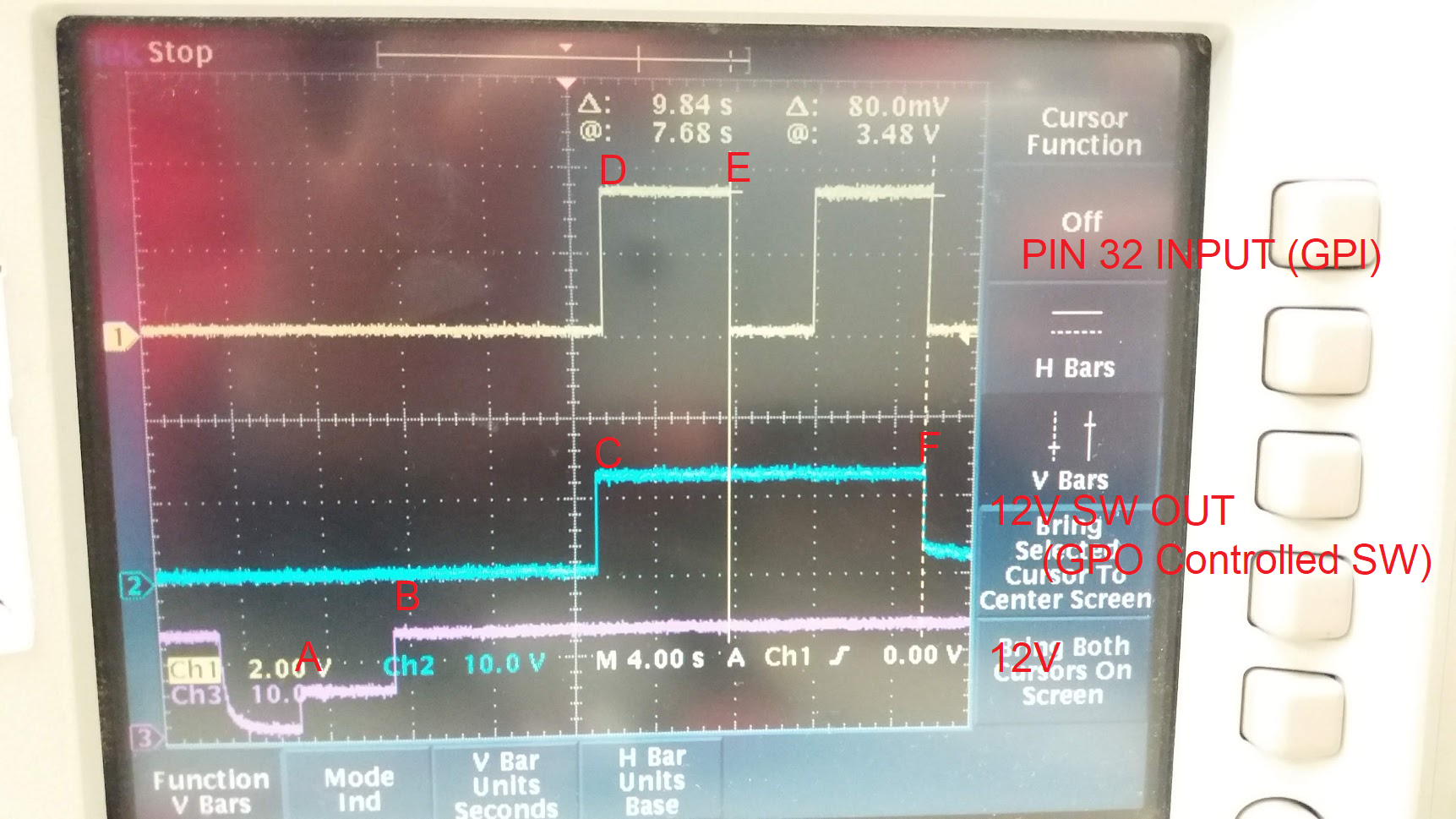
The following functionality is seen for the configuration shown above:


The yellow signal is the “32_GPI2_PWM2” which is active low so “NOT 32_GPI2_PWM2” is when the signal is at a high voltage.
The blue signal shows a 12V output which is enabled from the output of the GPO from this LGPO configuration (12V_LD_SW).
The 32_GPI2_PWM2 is low for 4 seconds but based off the explanation of the GPO behavior when not ignoring inputs during delay, this should be ignored and shouldn’t cause 12V_LD_SW to go low. It should also be noted that the 12V_LD_SW goes low 9.8s after the 32_GPI_PWM2 went low.

So our expectation for the trace would be the blue trace, controlled by the GPO, would never go low because the input yellow trace does not stay low sufficiently long.

  • Hi

    Thank you for reporting this. Do you have a waveform showing the LGPO output along with GPI and 12V?

    We will run some tests here to see what the problem could be. But if you can help provide your project file, it would be great to help us debug.

    Regards

    Yihe  

  • Attached is the requested trace.

    • (1) Yellow trace: GPI which comes from device powered by 12V (after load switch)
      (2) Blue trace: Output of 12V Load switch, which is controlled by UCD90120A GPO
      (3) Purple trace: 12V output of our regulator
    • A - Board is powered up, initially 12V power supply is off, but there is shoot through 5V (expected)
    • B - After some delay, 12V power supply is enabled, and comes up into proper regulation range
    • C - After the 12V power supply is detected good, after a delay, a load switch is thrown which enables 12V delivery to the load.
    • D - Shortly thereafter the load reacts by driving this input signal high (which is pin 32, our GPI of interest)
    • E - The powered device drives this signal low, and then high again. We want to ignore the "low" glitch in this period because it is not sufficiently long.
    • F - 9.8seconds after E, the switch (controlled by the UCD90120A) is turned off. We would have expected it not to be driven low here because yellow trace returned back to "high" state.  (Note that yellow trace is also goes low at this time because power is cut to the device when load switch is turned off).

    Again, our intended behavior is that "low" glitch of yellow trace beginning at "E" would be completely ignored by chip, unless it is sufficiently long. This does not appear to be the case.

    I have also attached our test configuration.

    test_stack_ti_test.xml

  • Hi

    Thank you very much for the waveform and files. I was able to duplicate the issue and explain why such behavior is observed

    For the state machine mode, each time only one AND PATH is evaluated. When device is out of reset, it evaluates AND PATH#1 first.

    A: AND PATH#1 logic is FALSE, so device outputs low and move to the AND PATH#2

    B: AND PATH#2 logic is TRUE due the 12V, device still outputs LOW since this a 10s delay and but it moves the AND PATH#1 immediately instead of after 10s delay.

    C: 10s delay is expired, output goes HIGH.

    D: The rising edge of the GPI does not change the logic of the AND PATH#1. so output stays HIGH and AND PATH#1 is still used

    E: AND PATH#1 logic is FALSE due to the falling edge of the GPI. device outputs HIGH since there is 10s delay, but it moves to the AND PATH2 immediately. This is the root cause of the issue.

    G: this is the next rising edge of the GPI after point E. At this moment, device is evaluating AND PATH#2 only and the GPI inputs has no impact on AND PATH#2. So there is no response for the G.

    F: 10s delay is expired, device outputs low and stay at AND PATH#2.

    What kind of logic do you want to achieve? We can see how to implement this without state machine mode

    Regards

    Yihe

  • Hello

    We haven't heard from you for a while and assumed that your question has been solved. Please reply if you need any further help.

    Regards

    Yihe