A related question is a question created from another question. When the related question is created, it will be automatically linked to the original question.
If you have a related question, please click the "Ask a related question" button in the top right corner. The newly created question will be automatically linked to this question.
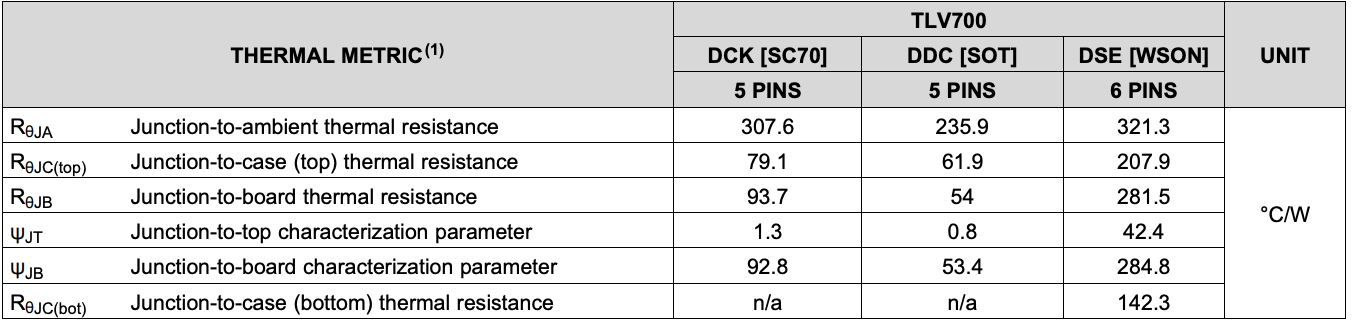
Your biggest challenge here is thermals. From 5V to 1.2V at 300mA, this is ~1.14W of power dissipation, even the best package for thermals would immediately shutdown:
RThetaJA is how to predict the junction temperature rise in the application. The power dissipated times this number is the temperature rise above the PCB ambient. For example, if you use the SOT package, the RThetaJA is 235.9 so with 1.14 of power this is 235.9C/W*1.14W or 258.9C. We would normally shut down around 160C.
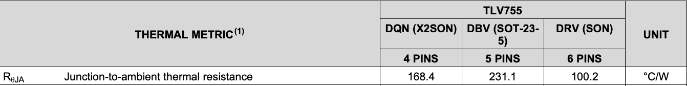
For much better performance, but still not recommended is something like the TLV755 in the SON package:
This has an RThetaJA of 100.2 which means the junction would rise ~114C above the PCB abient.
A device like the TLV758 could give you a bit more margin but it depends on your PCB ambient temp:
This reduces the temperature rise to ~1.14W*80/3C/W=91.5C.
If you can use a 3.3V rail instead of 5V for the input, that would help a lot.
That helps a lot but thermals are still a concern. (3.3V-1.2V)*0.3 equals 0.63W. If the load does demand 300mA of current, the device will likely enter into thermal shutdown.
That is much better, but keep in mind the is the temperature rise above the PCB ambient. So if your PCB ambient is ~25C, this would be a junction temperature of ~135C. Which may not shut down, but is above the maximum recommended operating temperature so it could impact long-term reliability.
I think it is safer to assume your enclosed PCB ambient is closer to 40-60C. But it would be good to confirm in your application. Here is a really good article on how your layout can impact thermal performance.