Because of the holidays, TI E2E™ design support forum responses will be delayed from Dec. 25 through Jan. 2. Thank you for your patience.

This thread has been locked.

If you have a related question, please click the "Ask a related question" button in the top right corner. The newly created question will be automatically linked to this question.

TPS2384: TPS2384 ports dying although they have TI recommended ESD/EFT/Surge protection.

Part Number: TPS2384

Hi.

We are developing switches with PoE capabilities. 

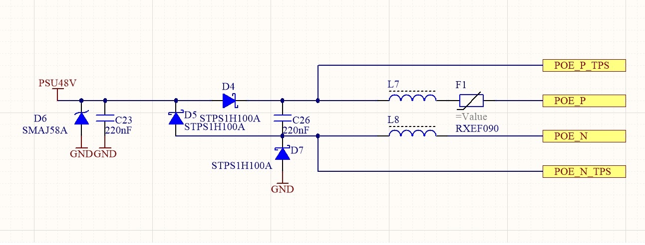
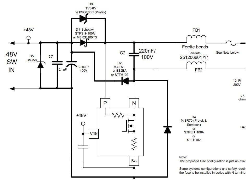
We implemented PoE protection scheme from TI SLVA233A application note.

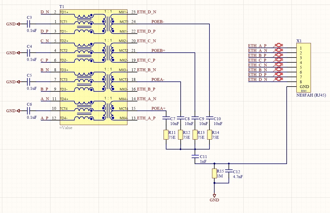
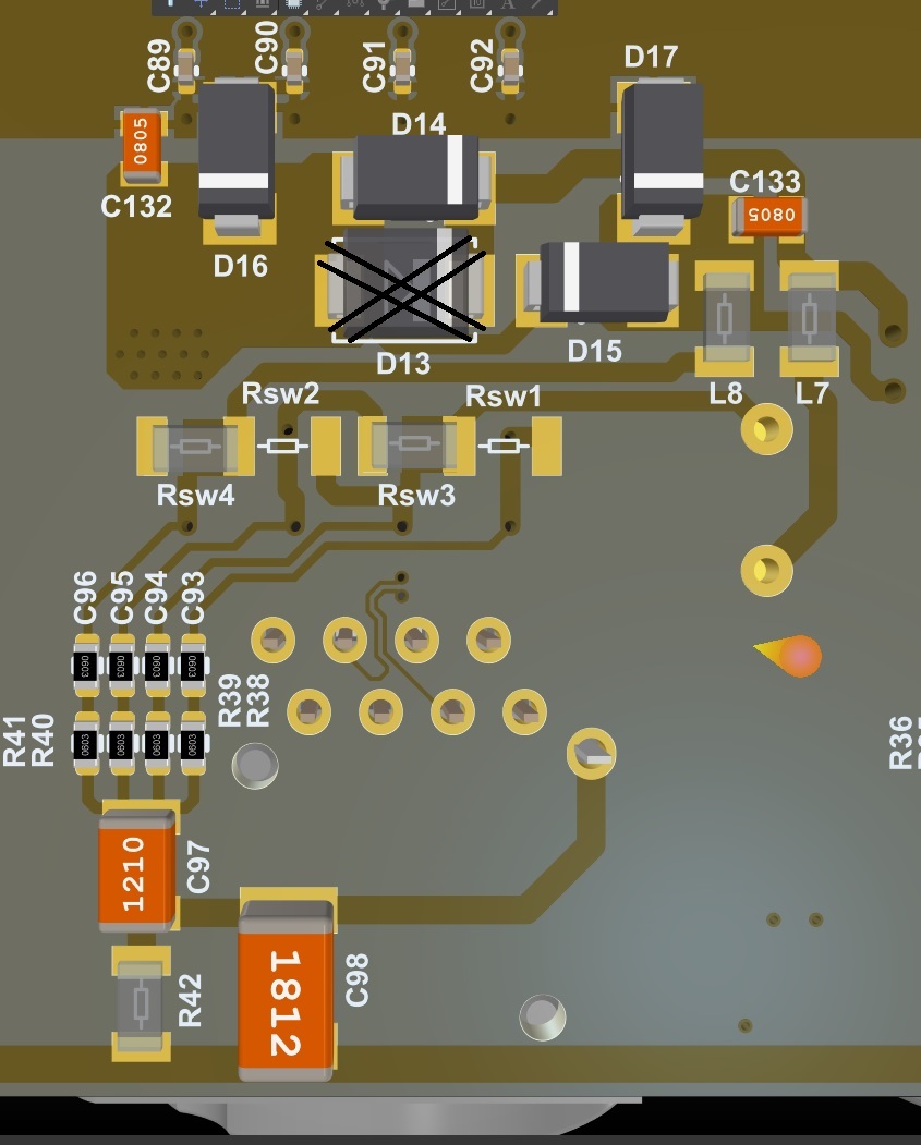
Below you can see images of schematics regarding protection and bob smith termination, and PCB.

Problem is that, we have encountered cases where TPS2384 ports have short circuit - the integrated MOSFET is shorted and it is dangerous for any non-PoE application to be connected to our device.

There have also been cases when TPS2384 port is dead - it won't turn on at all. 

I am still investigating the circuit board.

1. Can you please advise what could be improved? 

2. Is it important that bulk capacitance(in app note case it is 220uF) is close to the port? 

Some component specs: 

 C23, C26 - 08051C224KAT2A   'CAP 220nF ±10% 100V X7R -55÷125°C 0805

L7, L8 - 2512066017Y1 , 1A  600 Ohm @ 100MHz  ( as recommended by application note)

F1- Resettable fuse PPTC 1.8A/72V RXEF090 , Littelfuse

All other component part numbers are seen in image. TVS and schottky diodes are exactly same as recommended in TI app note.

  • Hi Karlis,

    The protection component should be placed close to the RJ45 connector or port power interface if a daughter board type of interface is used. What level of surge testing did you do? 1KV?

    You may also want to add some MOVs close to the RJ46 between ports and ground like shown in this app note:http://www.ti.com/lit/an/slua818/slua818.pdf

    Thanks.

    Best regards,

    Penny

  • Hi.

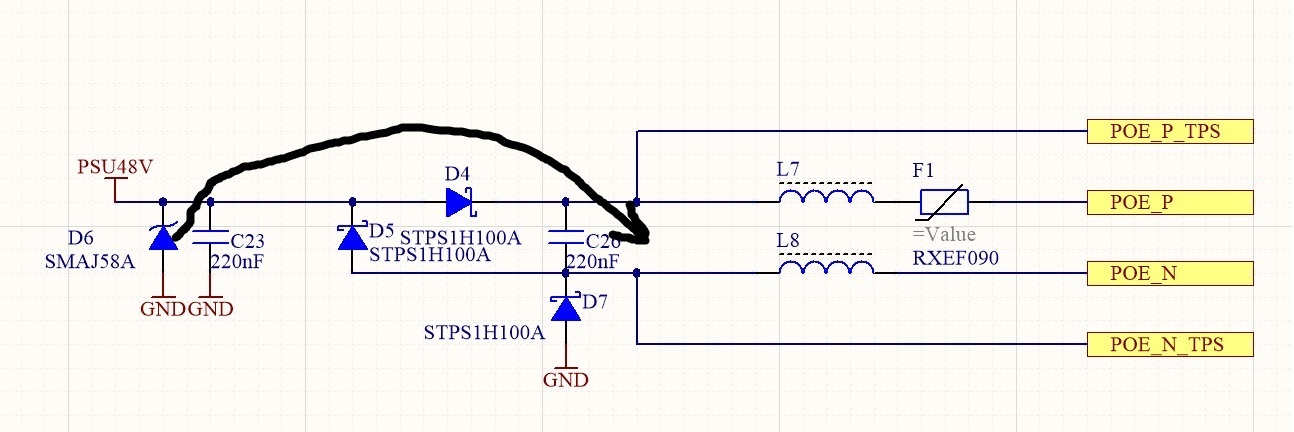
    We found out that TVS was located in the wrong place, which seems kinda obvious now....

    Old placement of D6 would work if there was zener in parallel with D4, which indeed would be the placement that TI application note recommends, but we had issues with recommended schematics thus we removed the zener which was in parallel with D4. Can't recall now exactly what issues we had now.

    I brought our boards to test house with the original scheme which was failing and scheme which has just the D6 TVS between the P and N .

    The original scheme failed surge test with +-500V . Improved scheme endured +-1500V Surge with no problems.

    Can you please advise me what would be disadvantages of schematics below compared to one in application note?

    Our new schematic:

    Application note recommendation:

  • Karlis,

    Moving the TVS from 48V to the port would increase the port level protection for both common mode and differential mode surge. But I still recommend you to add one theTVS and caps back between Vpwr and gnd for create a path for the current to go through during common mode surge. In addition, you can also consider adding MOVs between pairs to each ground to add more protection during common mode surge like we have in TIDA01411. Thanks. 

    Best regards,

    Penny