This thread has been locked.

If you have a related question, please click the "Ask a related question" button in the top right corner. The newly created question will be automatically linked to this question.

TPS74401-EP: TPS74401-EP powergood never goes high

Part Number: TPS74401-EP

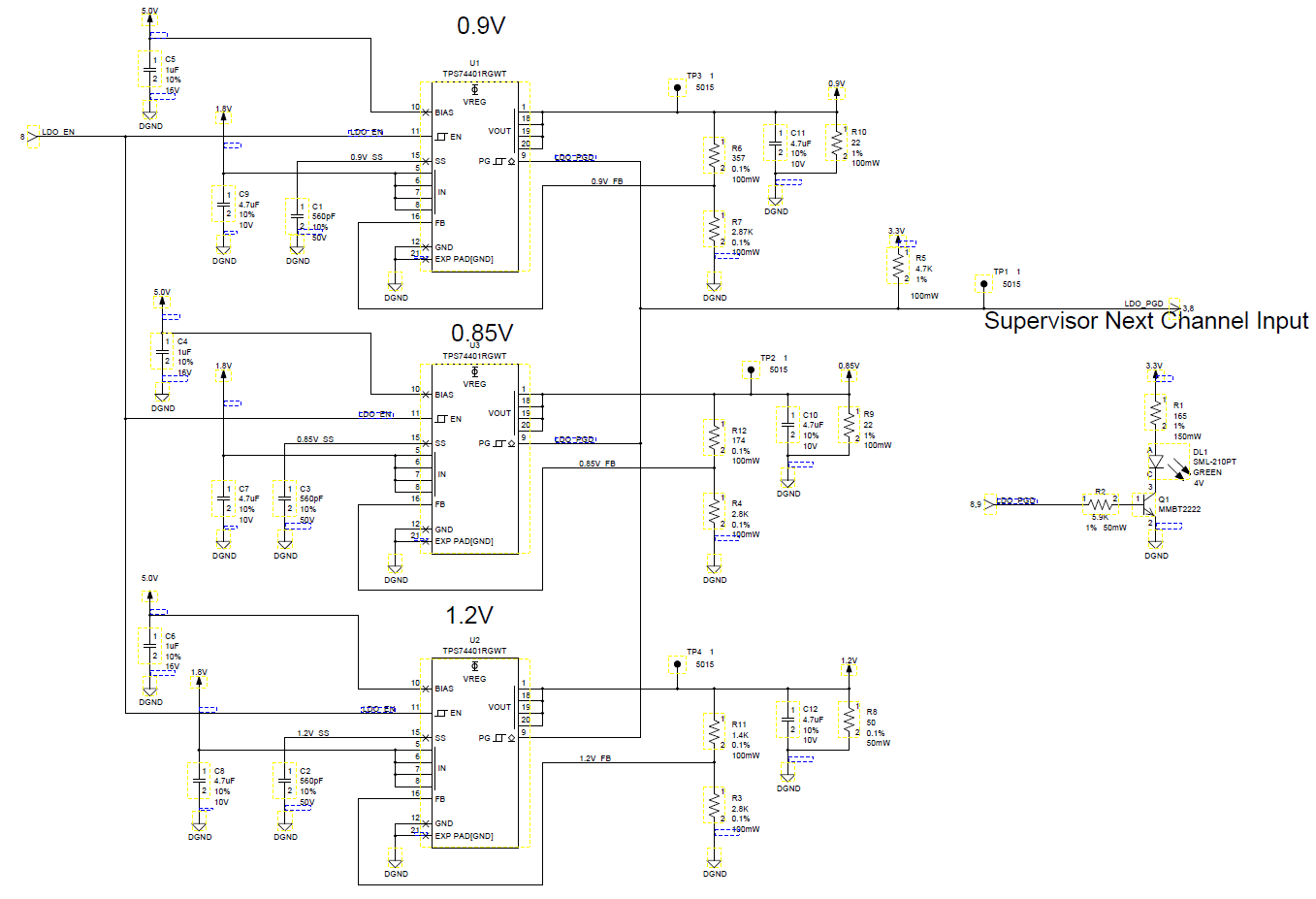
We are using the TPS74401RGWT LDO to generate 3 voltages (1.2V, 0.9V, and 0.85V) from a 1.8V input.

Our Vbias is at 5.0V with the recommended 1uF decoupling capacitor. Their PG outputs are all tied together with a 4.7K pull up to 3.3V. This same PG output is also used to drive an LED and as an input to a supervisor channel. The PG is tied to the base of an npn transistor throught a 5.9K resistor. The emitter is tied to ground and the collector is tied to the LED.

Simulating this in spice, we would expect a 2.15V active high PG when the rails finish ramping up.

However, the PG output is never going high.

We haven’t seen anything unexpected on the 1.8V and 5V rails via scope. The output voltages are also as expected on scope. The ramping rate on the voltage outputs is also as expected. We double checked the feedback resistors on the LDO, and they are correct.

We’ve used the exact same circuit in the past with the exception that the 3 LDO PG outputs were not tied together. They each had their own separate 10K pull ups and were connected to their own LED circuitry. The active high PG levels for this circuit measure ~800mV. Currently the PG output from the 3 LDOs tied together is measuring 50mV.

Any ideas on what might be the culprit here?

Thanks in advance,

Tijana

  • Hi Tijana, 

    When three PG are tired together, all three voltage rails need to pass PG threshold for the PG to give a high signal. The design of the PG is an open-drain output, the PG input impedance will become high when the output has passed the monitored voltage level. 

    Will you please upload the schematic for my evaluation? 

    Regards, 

    Jason Song

  • Hi Tijana,

    To add to Jason's request for a schematic we can look at I wanted to to confirm our understanding, all three output voltages are above their respective PG thresholds but the PG signal is only 50mV. If that is correct here are some questions we have 

    • How long was this signal measured after everything had settled?
      • There will be some propagation delay for the PG signal but if this was a steady state condition (or if the scope shot was at least zoomed out for a few hundred milliseconds) then that rules out propagation delay. 
    • If you disconnect the transistor/LED circuit (easiest way is probably to remove the 5.9k resistor) does the PG output go to the right voltage (~3.3V)
      • If Yes, then the transistor/LED circuit is drawing too much current through the 4.7k pull up resistor and causing the output to be lower than you desire.
      • If No, then it could be either a PCB assembly issue which has resulted in an unintended low resistance path to GND or possibly a damaged LDO (possibly ESD or EOS during assembly/testing of the application)

    • For clarification can you elaborate further on your statement "The active high PG levels for this circuit measure ~800mV." I'm unsure if you are referring to your old design where the 3 PG outputs were independently pulled up by 10K resistors or if you are seeing some boards with the 3 PG pins tied together that are working and some that are failing (with the working boards generating 800mV). 
      • How many failures have you had and what is the percentage of failing boards?
  • Thanks for the response!

    Jason/Kyle the schematic is attached, I hope this is still legible after posting. Note, please ignore the offsheet numbers as they were not updated.

    To answer Kyle's questions:

    The signal was measured after everything was settled.

    We can try taking the 5.9k resistor off.

    The path to GND resistance we measured was as expected.

    The 800mV active high PG levels are for the old design where all 3PG outputs were independently pulled up by 10K resistors.

    All of the boards we have tried with the current circuit (~4 boards) exhibit this issue with the PG output.

    Thanks again,

    Tijana

  • Hi Tijana,

    We reviewed the schematic, there isn't something obvious that is pulling current from the LDO_PGD rail. Since LDO_PGD is connecting to the NPN, will you please check if the NPN is correctly mounted to the board. Like Kyle suggested, will you try to remove the 5.9K ohms and see if the LDO_PGD can output the correct high voltage? 

    Regards, 
    Jason Song

  • Hi Jason and Kyle,

    We removed the 5.9K resistor and are still seeing the same behavior with the PG.

    Thanks,

    Tijana

  • Hi Tijana, 

    Will you also verify the 3.3V rail that all three PG pins are pulling up to is indeed up? Will you also check if you may have anything else on boards that could be pulling current from the 3.3V rail? 

    Regards,
    Jason Song

  • Thanks Jason!

    It was a sequencing issue with the 3.3V.