Other Parts Discussed in Thread: SM72442, SM72485
Hello,
I am an undergrad EE student building a solar charge controller that will power a 12.8V, 6Ah LiFePo battery from a 50W, 17 Vmpp solar panel by integrating the SM72442 and SM72295 to implement MPPT. I have been referencing the SM3320 SolarMagic and AN-2124 datasheets for my design. Attached below are the modifications I have made to the recommended application circuit for the SM72295. Both the solar panel and battery sizes are subject to change if necessary.
I am trying to test the operation of the SM72295 individually in each of its three modes (buck,boost,buck-boost) to verify that the circuit is operational before connecting it to the SM72442 and microcontroller. I would appreciate assistance with the following questions:
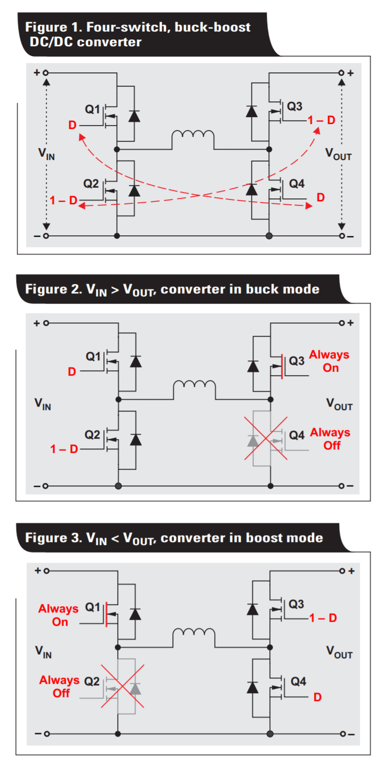
Could you please give an example for input signals required for LIA, HIA, HIB, LIB for testing these modes? I need assistance in determining the proper duty cycles and combination of switches that should be driven to test each mode. I have tried driving LIA,HIB with various duty cycles (D) and driving HIA,LIB with various duty cycles (1-D) at different input voltages as seen in the operation modes figure below, but I have not been able to see any output on the LOA,LOB,HOA,HOB pins for any input voltages up to 17V. How would I implement this using a function generator for testing? How can the on/off switches for buck and boost modes be effectively driven?
What input/output voltages would be best for testing to simulate the input voltage from the solar panel? I have powered VDD with 5V, and VCCA/VCCB with 10V.
Do dead-times need to be implemented in testing/ does the SM72295 implement hysterisis? Is there any other important start-up functionality that I am missing?
Thank you very much for your help with testing this design. Any recommendations for changes in part sizes, solar panel/battery sizes are greatly appreciated. I apologize for my lack of experience in this field, however, I am ready to learn from your responses.