This thread has been locked.

If you have a related question, please click the "Ask a related question" button in the top right corner. The newly created question will be automatically linked to this question.

BQ30Z554-R1: bq30z55DBTRRR3 DFW issue

Part Number: BQ30Z554-R1
Other Parts Discussed in Thread: BQ30Z55, BQ30Z55-R1

Hi Team,

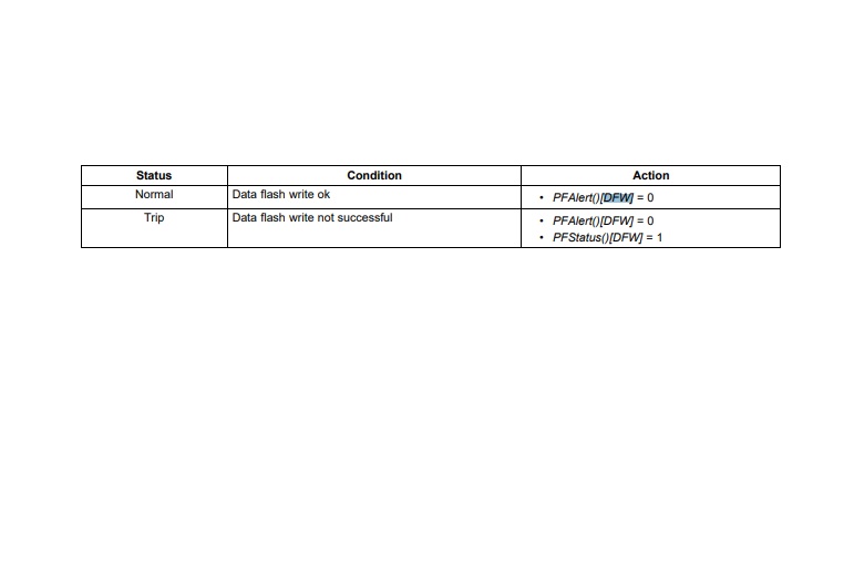
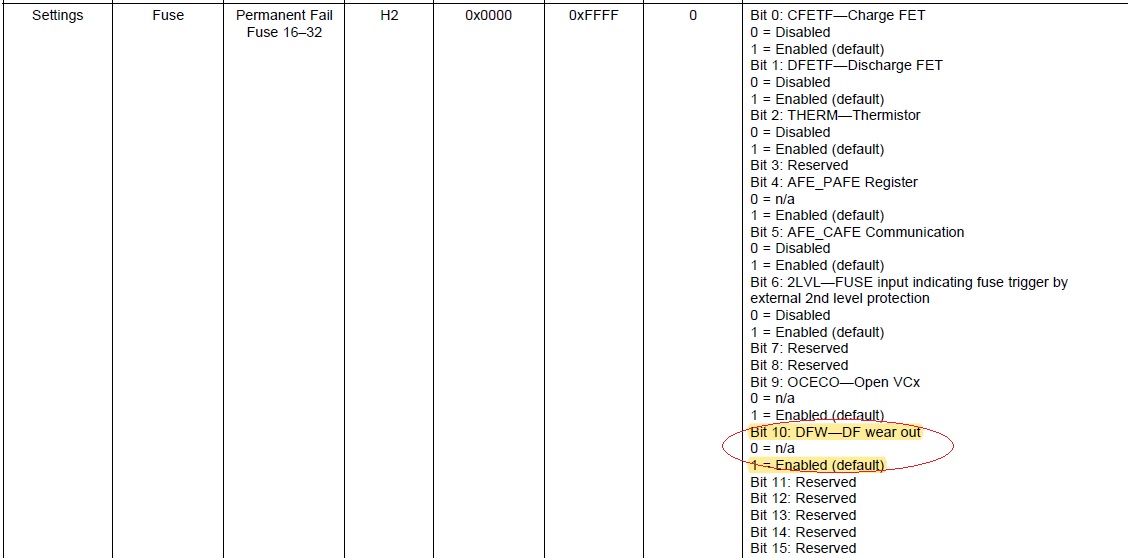
i have a problem,cusotmer use BQ30Z55DBTR-R3 for battery pack solution has been M/P,but DFW issue occur random.

was started by DFW, we have reset IC to clear the PF flag but DFW still happen, how can i avoid this problem?  or have any idea and suggestion for us.

attachment is schematic.

JM2SP068PPV600A_schematic (003).pdf

  • Hello Tommy,

    Sorry, can you clarify, what is DFW?

  • Hi Kang Kang,

    FYI.

  • Hi Kang Kang,

    have any idea or suggestion?

  • Hello Tommy,

    Can you check the cycle count and attach the gg file?

    The DF flash write not successful may mean that the flash is worn out. If this is the case, we should see a high cycle count number in the gg file.

  • Hi Kang Kang,

    but will this this complete charge and discharge increase once? does this have anything to do with the number of write? because we have confirmed that the cycle count of the PACK returned by DFW is more 100 and more than 200,but there are also less than 100, so i don't see this kind of problem appear in the datasheet after using DF flash write many times, so could you help confirm this issue?or is there any way to avoid this kind of problem.

  • Hello Tommy,

    This most likely means a dataflash is worn out. I am just wondering how many times this has been out in the field. I'll check the conditions for this bit setting.

  • Hello Tommy,


    During firmware operation, the gauge will try to update Ra tables or Qmax or lifetimes or some other impedance tracking parameter.

    The bit is set because when the gauge writes to flash, it will try to read back what it wrote. In this case, if the read back is different, the DFW bit is set.

    The most likely reason would be dataflash is worn out.

    Can you provide more information on how many packs are experiencing this failure? It could be that some of these packs may have been subject to multiple host side writes and caused the flash to wear out and gauge to unable to write to flash.

    Who is the end customer?

  • Hi Kang Kang,

    Can you provide more information on how many packs are experiencing this failure? 

    ans:11/55000 failure rate 0.02%, end custimer is Pegatron.

    if have DFW problem issue, will it cause IC damage? ic function be normal?

    as attached is customer the gg file, please reference.

    [Header]
    bq EVSW Version = 0.9.92	
    DeviceName = bq30z55R3 v0.36
    Time = 2020/3/2 �W�� 11:36:25	
    
    
    [State(Gas Gauging)]
    Qmax Cell 0 = 3143
    Qmax Cell 1 = 3125
    Qmax Cell 2 = 3200
    Qmax Cell 3 = 3200
    Qmax Pack = 3125
    Update Status = 0E
    Cell 0 Chg Voltage at EoC = 4051
    Cell 1 Chg Voltage at EoC = 4053
    Cell 2 Chg Voltage at EoC = 0
    Cell 3 Chg Voltage at EoC = 0
    Current at EoC = 37
    Avg I Last Run = -1341
    Avg P Last Run = -955
    Delta Voltage = 250
    Max Avg I Last Run = -1912
    Max Avg P Last Run = -1352
    [IT Cfg(Gas Gauging)]
    Load Select = 3
    Load Mode = 0
    Ra Filter = 80.0
    Ra Max Delta = 15
    Design Resistance = 110
    Reference Grid = 4
    Resistance Parameter Filter = 65142
    Term Voltage = 6400
    Term Voltage Delta = 300
    User Rate-mA = 0
    User Rate-cW = 0
    Reserve Cap-mAh = 70
    Reserve Cap-cWh = 44
    Remcap Smoothing Filter = 250
    Fast Scale Start SOC = 10
    [Current Thresholds(Gas Gauging)]
    Dsg Current Threshold = 50
    Chg Current Threshold = 20
    Quit Current = 10
    
    [R_a0(Ra Table)]
    Cell0 R_a flag = 0000
    Cell0 R_a 0 = 79
    Cell0 R_a 1 = 82
    Cell0 R_a 2 = 98
    Cell0 R_a 3 = 114
    Cell0 R_a 4 = 104
    Cell0 R_a 5 = 106
    Cell0 R_a 6 = 119
    Cell0 R_a 7 = 118
    Cell0 R_a 8 = 121
    Cell0 R_a 9 = 127
    Cell0 R_a 10 = 129
    Cell0 R_a 11 = 139
    Cell0 R_a 12 = 183
    Cell0 R_a 13 = 317
    Cell0 R_a 14 = 1081
    [R_a1(Ra Table)]
    Cell1 R_a flag = 0000
    Cell1 R_a 0 = 89
    Cell1 R_a 1 = 93
    Cell1 R_a 2 = 110
    Cell1 R_a 3 = 122
    Cell1 R_a 4 = 111
    Cell1 R_a 5 = 118
    Cell1 R_a 6 = 139
    Cell1 R_a 7 = 139
    Cell1 R_a 8 = 141
    Cell1 R_a 9 = 145
    Cell1 R_a 10 = 145
    Cell1 R_a 11 = 150
    Cell1 R_a 12 = 170
    Cell1 R_a 13 = 275
    Cell1 R_a 14 = 935
    [R_a2(Ra Table)]
    Cell2 R_a flag = FF55
    Cell2 R_a 0 = 66
    Cell2 R_a 1 = 69
    Cell2 R_a 2 = 82
    Cell2 R_a 3 = 104
    Cell2 R_a 4 = 80
    Cell2 R_a 5 = 73
    Cell2 R_a 6 = 86
    Cell2 R_a 7 = 75
    Cell2 R_a 8 = 76
    Cell2 R_a 9 = 76
    Cell2 R_a 10 = 73
    Cell2 R_a 11 = 83
    Cell2 R_a 12 = 89
    Cell2 R_a 13 = 132
    Cell2 R_a 14 = 452
    [R_a3(Ra Table)]
    Cell3 R_a flag = FF55
    Cell3 R_a 0 = 66
    Cell3 R_a 1 = 69
    Cell3 R_a 2 = 82
    Cell3 R_a 3 = 104
    Cell3 R_a 4 = 80
    Cell3 R_a 5 = 73
    Cell3 R_a 6 = 86
    Cell3 R_a 7 = 75
    Cell3 R_a 8 = 76
    Cell3 R_a 9 = 76
    Cell3 R_a 10 = 73
    Cell3 R_a 11 = 83
    Cell3 R_a 12 = 89
    Cell3 R_a 13 = 132
    Cell3 R_a 14 = 452
    [R_a0x(Ra Table)]
    xCell0 R_a flag = 0055
    xCell0 R_a 0 = 79
    xCell0 R_a 1 = 82
    xCell0 R_a 2 = 98
    xCell0 R_a 3 = 114
    xCell0 R_a 4 = 104
    xCell0 R_a 5 = 106
    xCell0 R_a 6 = 119
    xCell0 R_a 7 = 120
    xCell0 R_a 8 = 123
    xCell0 R_a 9 = 129
    xCell0 R_a 10 = 131
    xCell0 R_a 11 = 141
    xCell0 R_a 12 = 186
    xCell0 R_a 13 = 322
    xCell0 R_a 14 = 1099
    [R_a1x(Ra Table)]
    xCell1 R_a flag = 0055
    xCell1 R_a 0 = 89
    xCell1 R_a 1 = 93
    xCell1 R_a 2 = 110
    xCell1 R_a 3 = 122
    xCell1 R_a 4 = 111
    xCell1 R_a 5 = 118
    xCell1 R_a 6 = 139
    xCell1 R_a 7 = 145
    xCell1 R_a 8 = 147
    xCell1 R_a 9 = 151
    xCell1 R_a 10 = 151
    xCell1 R_a 11 = 156
    xCell1 R_a 12 = 177
    xCell1 R_a 13 = 287
    xCell1 R_a 14 = 975
    [R_a2x(Ra Table)]
    xCell2 R_a flag = FFFF
    xCell2 R_a 0 = 66
    xCell2 R_a 1 = 69
    xCell2 R_a 2 = 82
    xCell2 R_a 3 = 104
    xCell2 R_a 4 = 80
    xCell2 R_a 5 = 73
    xCell2 R_a 6 = 86
    xCell2 R_a 7 = 75
    xCell2 R_a 8 = 76
    xCell2 R_a 9 = 76
    xCell2 R_a 10 = 73
    xCell2 R_a 11 = 83
    xCell2 R_a 12 = 89
    xCell2 R_a 13 = 132
    xCell2 R_a 14 = 452
    [R_a3x(Ra Table)]
    xCell3 R_a flag = FFFF
    xCell3 R_a 0 = 66
    xCell3 R_a 1 = 69
    xCell3 R_a 2 = 82
    xCell3 R_a 3 = 104
    xCell3 R_a 4 = 80
    xCell3 R_a 5 = 73
    xCell3 R_a 6 = 86
    xCell3 R_a 7 = 75
    xCell3 R_a 8 = 76
    xCell3 R_a 9 = 76
    xCell3 R_a 10 = 73
    xCell3 R_a 11 = 83
    xCell3 R_a 12 = 89
    xCell3 R_a 13 = 132
    xCell3 R_a 14 = 452
    
    [Manufacturer Data(System Data)]
    ManufacturerInfo = 150422-A
    [Integrity(System Data)]
    Data Flash Checksum = 0000
    
    [Data(SBS Configuration)]
    Remaining AH Cap. Alarm = 300
    Remaining WH Cap. Alarm = 198
    Remaining Time Alarm = 10
    Initial Battery Mode = 8081
    Design Voltage = 7600
    Specification Information = 0031
    Manufacture Date = 20-Oct-2015
    Serial Number = 0065
    Cycle Count = 92
    Cycle Count Percentage = 60
    Max Error Limit = 100
    Design Capacity mAh = 3200
    Design Capacity cWh = 2432
    Manufacturer Name = JMS
    Device Name = RSE001
    Device Chemistry = LION
    [FD(SBS Configuration)]
    Set Voltage Threshold = 3000
    Clear Voltage Threshold = 3100
    Set % RSOC Threshold = 0
    Clear % RSOC Threshold = 5
    [FC(SBS Configuration)]
    Set Voltage Threshold = 4200
    Clear Voltage Threshold = 4100
    Set % RSOC Threshold = 100
    Clear % RSOC Threshold = 95
    [TDA(SBS Configuration)]
    Set Voltage Threshold = 3200
    Clear Voltage Threshold = 3300
    Set % RSOC Threshold = 10
    Clear % RSOC Treshold = 15
    [TCA(SBS Configuration)]
    Set Voltage Threshold = 4200
    Clear Voltage Threshold = 4100
    Set % RSOC Threshold = 100
    Clear % RSOC Threshold = 95
    [Max Error(SBS Configuration)]
    Time Cycle Equivalent = 24
    Cycle Delta = 0.05
    
    [CUV(Protections)]
    Threshold = 3000
    Delay = 1
    Recovery = 3200
    [CUVC(Protections)]
    Threshold = 2900
    Delay = 2
    Recovery = 3000
    [COV(Protections)]
    Threshold Low Temp = 4140
    Threshold Standard Temp = 4140
    Threshold High Temp = 4140
    Threshold Rec Temp = 4140
    Delay = 1
    Recovery Low Temp = 3950
    Recovery Standard Temp = 3950
    Recovery High Temp = 3950
    Recovery Rec Temp = 3950
    [OCC1(Protections)]
    Threshold = 2500
    Delay = 6
    [OCC2(Protections)]
    Threshold = 3200
    Delay = 2
    [OCC(Protections)]
    Recovery Threshold = -50
    Recovery Delay = 8
    [OCD1(Protections)]
    Threshold = -4850
    Delay = 6
    [OCD2(Protections)]
    Threshold = -5200
    Delay = 2
    [OCD(Protections)]
    Recovery Threshold = 20
    Recovery Delay = 8
    [OLD(Protections)]
    Threshold = 05
    Delay = 0F
    Latch Limit = 0
    Counter Dec Delay = 10
    Recovery = 8
    Reset = 15
    [SCC(Protections)]
    Threshold = 82
    Latch Limit = 0
    Counter Dec Delay = 10
    Recovery = 5
    Reset = 15
    [SCD1(Protections)]
    Threshold = 82
    [SCD2(Protections)]
    Threshold = A4
    [SCD(Protections)]
    Latch Limit = 0
    Counter Dec Delay = 10
    Recovery = 8
    Reset = 15
    [OTC(Protections)]
    Threshold = 55.0
    Delay = 2
    Recovery = 50.0
    [OTD(Protections)]
    Threshold = 80.0
    Delay = 2
    Recovery = 70.0
    [OTF(Protections)]
    Threshold = 80.0
    Delay = 2
    Recovery = 70.0
    [HWD(Protections)]
    Delay = 10
    [PTO(Protections)]
    Charge Threshold = 2000
    Suspend Threshold = 1800
    Delay = 1800
    Reset = 2
    [CTO(Protections)]
    Charge Threshold = 2500
    Suspend Threshold = 2000
    Delay = 54000
    Reset = 2
    [OC(Protections)]
    Threshold = 300
    Recovery = 20
    RSOC Recovery = 90
    [CHGV(Protections)]
    Threshold = 500
    Delay = 30
    Recovery = -500
    [CHGC(Protections)]
    Threshold = 500
    Delay = 2
    Recovery = 100
    
    [CUV(Permanent Fail)]
    Threshold = 2000
    Delay = 2
    [COV(Permanent Fail)]
    Threshold = 4300
    Delay = 2
    [CUDEP(Permanent Fail)]
    Threshold = 2000
    Delay = 2
    [OTCE(Permanent Fail)]
    Threshold = 91.0
    Delay = 2
    [OTF(Permanent Fail)]
    Threshold = 100.0
    Delay = 2
    [QIM(Permanent Fail)]
    Delta Threshold = 2200
    Delay = 2
    [CB(Permanent Fail)]
    Max Threshold = 240
    Delta Threshold = 40
    Delay = 2
    [VIMR(Permanent Fail)]
    Check Voltage = 3700
    Check Current = 10
    Delta Threshold = 300
    Delta Delay = 2
    Duration = 100
    [VIMA(Permanent Fail)]
    Check Voltage = 3700
    Check Current = 50
    Delta Threshold = 370
    Delay = 2
    [IMP(Permanent Fail)]
    Delta Threshold = 300
    Max Threshold = 400
    Ra Update Counts = 2
    [CD(Permanent Fail)]
    Threshold = 0
    Delay = 2
    [CFET(Permanent Fail)]
    OFF Threshold = 20
    OFF Delay = 2
    [DFET(Permanent Fail)]
    OFF Threshold = -20
    OFF Delay = 2
    [TH(Permanent Fail)]
    ADC Delay = 10
    [FUSE(Permanent Fail)]
    Threshold = 5
    Delay = 2
    [AFER(Permanent Fail)]
    Threshold = 100
    Delay Period = 2
    Compare Period = 5
    [AFEC(Permanent Fail)]
    Threshold = 100
    Delay Period = 5
    [2LVL(Permanent Fail)]
    Delay = 2
    [OCECO(Permanent Fail)]
    Threshold = 5000
    Delay = 2
    
    [Device Status Data(PF Status)]
    Safety Alert 0-15 = 0001
    Safety Status 0-15 = 0001
    PF Alert 0-15 = 0000
    PF Status 0-15 = 0000
    Safety Alert 16-31 = 0000
    Safety Status 16-31 = 0000
    PF Alert 16-31 = 0000
    PF Status 16-31 = 0400
    Operation Status 0-15 = 0000
    Operation Status 16-31 = 0000
    Charging Status 0-15 = 0000
    Charging Status 16-23 = 00
    Gauging Status = 0000
    [Device Voltage Data(PF Status)]
    Cell Voltage 0 = 0
    Cell Voltage 1 = 0
    Cell Voltage 2 = 0
    Cell Voltage 3 = 0
    Battery Direct Voltage = 0
    Pack Voltage = 0
    [Device Current Data(PF Status)]
    Current = 0
    [Device Temperature Data(PF Status)]
    Internal Temperature = -273.2
    External 1 Temperature = -273.2
    External 2 Temperature = -273.2
    [Device Gauging Data(PF Status)]
    Cell0 Dod0 = 0
    Cell1 Dod0 = 0
    Cell2 Dod0 = 0
    Cell3 Dod0 = 0
    Passed Charge = 0
    [AFE Regs(PF Status)]
    AFE Status = 00
    AFE State Control = 00
    AFE Control = 00
    AFE Output Status = 00
    AFE Function Control = 00
    AFE Cell Select = 00
    AFE OCDV = 00
    AFE OCDT = 00
    AFE SCC = 00
    AFE SCD1 = 00
    AFE SCD2 = 00
    AFE REF TRIM = 00
    
    [Safety Status(Black Box)]
    1st Status Status 0-15 = 0000
    1st Safety Status 16-31 = 0000
    1st Time to Next Event = 0
    2nd Safety Status 0-15 = 0000
    2nd Safety Status 16-31 = 0000
    2nd Time to Next Event = 0
    3rd Safety Status 0-15 = 0000
    3rd Safety Status 16-31 = 0000
    3rd Time to Next Event = 0
    [PF Status(Black Box)]
    1st PF Status 0-15 = 0000
    1st PF Status 16-31 = 0400
    1st Time to Next Event = 0
    2nd PF Status 0-15 = 0000
    2nd PF Status 16-31 = 0000
    2nd Time to Next Event = 0
    3rd PF Status 0-15 = 0000
    3rd PF Status 16-31 = 0000
    3rd Time to Next Event = 0
    
    [Voltage(Lifetimes)]
    Max Cell Voltage 0 = 4060
    Max Cell Voltage 1 = 4060
    Max Cell Voltage 2 = 0
    Max Cell Voltage 3 = 0
    Min Cell Voltage 0 = 2720
    Min Cell Voltage 1 = 2700
    Min Cell Voltage 2 = 0
    Min Cell Voltage 3 = 0
    Max Delta Cell Voltage = 440
    [Current(Lifetimes)]
    Max Charge Current = 1400
    Max Discharge Current = 1400
    Max Avg Dsg Current = 800
    Max Avg Dsg Power = 9
    [Safety Events(Lifetimes)]
    No Of Cov Events = 0
    Last Cov Event = 0
    No Of Cuv Events = 40
    Last Cuv Event = 84
    No Of Ocd1 Events = 0
    Last Ocd1 Event = 0
    No Of Ocd2 Events = 0
    Last Ocd2 Event = 0
    No Of Occ1 Events = 0
    Last Occ1 Event = 0
    No Of Occ2 Events = 0
    Last Occ2 Event = 0
    No Of Old Events = 0
    Last Old Event = 0
    No Of Scd Events = 0
    Last Scd Event = 0
    No Of Scc Events = 0
    Last Scc Event = 0
    No Of Otc Events = 0
    Last Otc Event = 0
    No Of Otd Events = 0
    Last Otd Event = 0
    No Of Otf Events = 0
    Last Otf Event = 0
    [Charging Events(Lifetimes)]
    No Valid Charge Term = 2040
    Last Valid Charge Term = 92
    [Gauging Events(Lifetimes)]
    No Of Qmax Updates = 0
    Last Qmax Update = 68
    No Of Ra Updates = 0
    Last Ra Update = 0
    No Of Ra Disable = 72
    Last Ra Disable = 92
    [Power Events(Lifetimes)]
    No Of Shutdowns = 2
    [Cell Balancing(Lifetimes)]
    Cb Time Cell 0 = 86
    Cb Time Cell 1 = 136
    Cb Time Cell 2 = 0
    Cb Time Cell 3 = 0
    [Temperature(Lifetimes)]
    Max Temp Cell = 46
    Min Temp Cell = -1
    Max Delta Cell Temp = 3
    Max Temp Int Sensor = 45
    Min Temp Int Sensor = 0
    Max Temp Fet = 0
    [Time(Lifetimes)]
    Total Fw Runtime = 20900
    Time Spent In UT = 0
    Time Spent In LT = 1740
    Time Spent In STL = 12166
    Time Spent In RT = 0
    Time Spent In STH = 6990
    Time Spent In HT = 0
    Time Spent In OT = 0
    
    [Fuse(Settings)]
    PF Fuse 0-15 = 0013
    PF Fuse 16-31 = 0407
    Min Blow Fuse Voltage = 5000
    [Manufacturing(Settings)]
    Manufacturing Status = 01F8
    [Protection(Settings)]
    Enabled Protections 0-15 = 3FFF
    Enabled Protections 16-31 = 0000
    [Permanent Failure(Settings)]
    Enabled PF 0-15 = 1813
    Enabled PF 16-31 = 040F
    [Configuration(Settings)]
    Protection Configuration = 00
    Temperature Configuration = 1006
    Charging Configuration = 09
    System Configuration = 003D
    Gauging Configuration = 06CE
    Sbs Configuration = 20
    Sbs Data Config. 0-15 = 0CCC
    Sbs Data Config. 16-23 = CC
    [AFE(Settings)]
    AFE State Control = 00
    
    [Power(Power)]
    Valid Update Voltage = 4000
    [Shutdown(Power)]
    Shutdown Voltage = 2700
    Shutdown Time = 10
    PF Shutdown Voltage = 2000
    PF Shutdown Time = 10
    Charger Present Threshold = 3000
    [Sleep(Power)]
    Sleep Current = 10
    Voltage Time = 5
    Current Time = 20
    Wake = 00
    [Ship(Power)]
    Delay = 5
    
    [Temperature Ranges(Advanced Charge Algorithm)]
    T1 Temp = -5
    T2 Temp = 10
    T5 Temp = 20
    T6 Temp = 25
    T3 Temp = 50
    T4 Temp = 60
    Hysteresis Temp = 5
    [Low Temp Charging(Advanced Charge Algorithm)]
    Voltage = 4100
    Current Low = 1600
    Current Med = 1600
    Current High = 1600
    [Standard Temp Charging(Advanced Charge Algorithm)]
    Voltage = 4100
    Current Low = 2500
    Current Med = 2500
    Current High = 2500
    [High Temp Charging(Advanced Charge Algorithm)]
    Voltage = 4100
    Current Low = 1600
    Current Med = 1600
    Current High = 1600
    [Rec Temp Charging(Advanced Charge Algorithm)]
    Voltage = 4100
    Current Low = 2500
    Current Med = 2500
    Current High = 2500
    [Pre-Charging(Advanced Charge Algorithm)]
    Current = 320
    [Maintenance Charging(Advanced Charge Algorithm)]
    Current = 160
    [Voltage Range(Advanced Charge Algorithm)]
    Charging Voltage Low = 2700
    Charging Voltage Med = 3600
    Charging Voltage High = 4000
    Charging Voltage Hysteresis = 100
    [Termination Config(Advanced Charge Algorithm)]
    Charge Term Taper Current = 160
    Charge Term Voltage = 150
    [Cell Balancing Config(Advanced Charge Algorithm)]
    Bal Time/mAh Cell 0 = 359
    Bal Time/mAh Cell 1-3 = 502
    Min Start Balance Delta = 3
    Relax Balance Interval = 18000
    Min Rsoc for Balancing = 80
    [Charging Rate of Change(Advanced Charge Algorithm)]
    Current Rate = 1
    Voltage Rate = 1
    [Charge Loss Compensation(Advanced Charge Algorithm)]
    CCC Current Threshold = 3520
    CCC Voltage Threshold = 4200
    
    [Voltage(Calibration)]
    Cell Scale 0 = 20571
    Cell Scale 1 = 20609
    Cell Scale 2 = 20609
    Cell Scale 3 = 20609
    Pack Gain = 53747
    BAT Gain = 48893
    [Current(Calibration)]
    CC Gain = 0.941
    Capacity Gain = 280585.812
    [Current Offset(Calibration)]
    CC Offset = -8066
    Coulomb Counter Offset Samples = 64
    Board Offset = 0
    [Temperature(Calibration)]
    Internal Temp Offset = 6.3
    External1 Temp Offset = -.2
    External2 Temp Offset = 0.4
    [Internal Temp Model(Calibration)]
    Int Coeff 1 = 0
    Int Coeff 2 = 0
    Int Coeff 3 = -11136
    Int Coeff 4 = 5754
    Int Minimum AD = 0
    Int Maximum Temp = 5754
    [Cell Temperature Model(Calibration)]
    Coeff a1 = -12598
    Coeff a2 = 20755
    Coeff a3 = -19272
    Coeff a4 = 28020
    Coeff a5 = 789
    Coeff b1 = -245
    Coeff b2 = 470
    Coeff b3 = -3352
    Coeff b4 = 5022
    Rc0 = 11703
    Adc0 = 11703
    Rpad = 0
    Rint = 0
    [Fet Temperature Model(Calibration)]
    Coeff a1 = -12598
    Coeff a2 = 20755
    Coeff a3 = -19272
    Coeff a4 = 28020
    Coeff a5 = 789
    Coeff b1 = -245
    Coeff b2 = 470
    Coeff b3 = -3352
    Coeff b4 = 5022
    Rc0 = 11703
    Adc0 = 11703
    Rpad = 0
    Rint = 0
    [Filter(Calibration)]
    Cell Voltage 1 = 145
    Cell Voltage 2 = 145
    Cell Voltage 3 = 145
    Cell Voltage 4 = 145
    Pack Voltage Out = 10
    Direct Battery Voltage = 10
    Summed Battery Voltage = 145
    Cell Temperature = 145
    FET Temperature = 145
    [Current Deadband(Calibration)]
    Deadband = 3
    Coulomb Counter Deadband = 34
    

  • Hello Tommy,

    This does look like a potential flash corruption.

    Are you able to still communicate with the "DFW bit set packs"?

  • Hi Kang Kang,

    if DFW is turn off(n/a), what other offect will it have?

  • Hello Tommy,

    I believe it just means you will not get a PF when the DF writes are worn out.

    I don't know if this is particularly recommended. The 1 is enabled by default.

  • Hi Kang Kang,

    So don't you recommend it?

  • Hello Tommy,

    The default value is "1". I don't think you should set it to "0" without knowing your system well enough.

  • Hi Kang Kang,

    DFW caused by the internal Gauge IC and can't get PF,what is the relation with the system?may i know have any risk?

    I believe it just means you will not get a PF when the DF writes are worn out.==>because the customer has concern, is it related with the system?

  • Hello Tommy,

    A potential cause is that if the dataflash is worn out and your system does not know about it, it could mean no alert will be triggered. You will have to assess system level behavior on your side.

    It could be Ra tables updating incorrectly and Qmax updating incorrectly.

  • Hi Kang Kang,

    thank for your great support.

    several issue as follows:

    are there different program version for BQ30Z55 series?is there ECN?

    how to berify that the flash can be write for more than 20k cycles, and how often will it be write?is there a file description for the number of flash memory write/ calculate?

    look forward to your reply.

  • Hi Kang Kang,

    any idea or information?

  • why do you have

    [CUV(Protections)]
    Threshold = 3000
    Delay = 1
    Recovery = 3200

    and here

    [Power(Power)]
    Valid Update Voltage = 4000
    [Shutdown(Power)]
    Shutdown Voltage = 2700

    ????????


  • Поэтому у вас есть

    [CUV (Защита)]
    Порог = 3000
    Задержка  = 1
    Восстановление = 3200

    и здесь

    [Power (Power)]
    Действительное напряжение обновления = 4000
    [Shutdown (Power)]
    Напряжение отключения = 2700

    ????????


  • Hi Sir,

    I can't see your narrative.because it is garbled.

    My question is as follows:

    are there different program version for BQ30Z55 series?is there ECN?

    how to berify that the flash can be write for more than 20k cycles, and how often will it be write?is there a file description for the number of flash memory write/ calculate?

  • Hello,

    It is just the latest from ti.com.

  • Hi Kang Kang,

    sorry,what is mean and I’m not following.
    could you help customer the following question?

    are there different program version for BQ30Z55 series?is there ECN?

    how to berify that the flash can be write for more than 20k cycles, and how often will it be write?is there a file description for the number of flash memory write/ calculate?

  • Hello,

    I would go by the DS spec. There's no file for how often flash writes. We write flash periodically for Qmax and Ra updates throughout the life of the battery pack.

    I see one version of the bq30z55-R1 on ti.com