This thread has been locked.

If you have a related question, please click the "Ask a related question" button in the top right corner. The newly created question will be automatically linked to this question.

LM3671MF-1.8EV: Regulator putting out 4V instead of 3.3V

Part Number: LM3671MF-1.8EV

We've been getting returns on some units after they've been in the field for ~6 months.
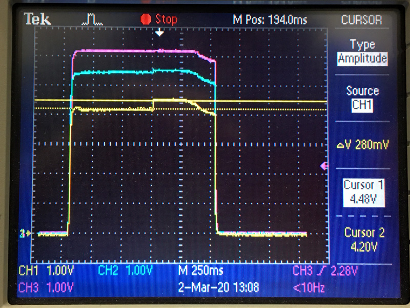
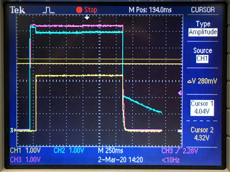
Many of them show that the LM3671 output is 4.1V instead of 3.3V. This in turn lies between the operating limit and absolute max for another chip in our design, so its outputs are burning out.

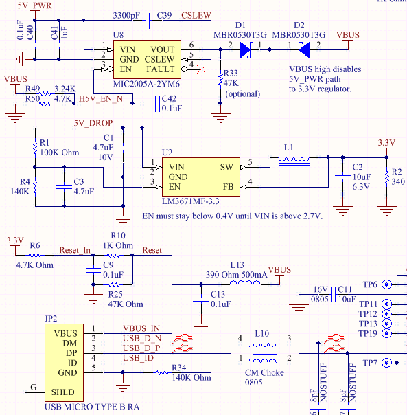
What could cause an LM3671MF-3.3/NOPB to put out 4V?

We have 2 possible 5V inputs (USB and HDMI 5V pins) that feed the regulator through diodes, so it should only see at most ~4.7V. We also have each of them tied to a CM1293A-04SO pin for ESD protection.

Worst case, we might have to redesign with a regulator with a wider input voltage range and higher ESD protection rating... but this product has already been selling for a few years.

If there is a flaw in our design, we would appreciate a fix, or at least some possible mitigation advice.

Thanks!

  • Hi Anthony,

    Could you provide more detail about schematics, layout, external components used and operating conditions like temp, load conditions?

    If information is confidential, I would recommend sharing through the e-mail for further information. 

    Best regards,

    Tanvee

  • 5V_PWR comes from an HDMI cable. VBUS IN comes from a USB cable.

    My worry is that a spike or bad supply could cause problems, despite having ESD protection and ferrites in the design to prevent it. Each of these signals are attached to pins of CM1293A-04SO ESD protection chips.

    The max rating of LM3671MF-3.3/NOPB is 6V, which isn't much more than the 5V nominal value of the incoming voltages.

    What I wasn't able to get out of the TI Helpdesk was *what* could cause this device to break in a way that it starts putting out 4V instead of 3.3V.

    What is it inside the chip that could break in a way to make this happen. If I knew that, I might have a better idea of what to do about it.

  • Hi Anthony,

    The schematic looks okay. It seems the application might getting surge on the input side. could you measure the input voltage and output voltage with inductor current during enable on and enable disable? Waveform would provide a better understanding of the issue. 

    Best regards,

    Tanvee  

  • The thing is, since these are consumer products, I don't know what the source voltage look like in the field cases where these have failed . We tested these for months in the lab and never had this problem. So really, I'd like to know what susceptibilities there might be inside the chip (or what the relevant portions of the chip schematic look like).

    I wrote a Labview program to tell a bench supply to cycle between 0V (1s), 6V (200-300ms), and 5V (4s), and ran it several hundred times to see if I could induce a failure in the chip similar to what we're seeing. The chip never failed.6V is the absolute maximum rating of the chip, but it also goes through a diode before the regulator, so I need to use the other bench supply output that is capable of >6V.

    So here's a scope capture of 6V. I'll get back to you with one that shows the actual regulator input at 6V or greater....

  • Hi Anthony,

    According to the above explanation, the problem looks more related to the system than the device. Are you measuring on the customer product? Normally, HDMI/USB source require the short circuit protection for the application. Is there is pre-requirement for this application?  Because this device does not have an internal short circuit feature. 

    Best regards,

    Tanvee

  • Hi Tanvee,

    I modified my Labview to allow higher voltages using the 25V channel, then ran the power cycling of our device with a 6.8V, 250ms "spike" at power up, which is 6.45V after the diode drop, directly into the regulator.
    (See scope screen capture, below.)

    This is well above the device's absolute maximum rating. After the "spike", I set it to 5V, and cycled it every 5s, long enough for the sink to bring up video so I could see it was working.

    I ran this test well over 300 times on one of our units, and it worked fine.
    Magenta: 6.8V USB power in.  Cyan: 6.45V into the regulator.   Yellow: 3.3V regulator output.

    I don't see any irregularities on the 3.3V regulator output. I might try raising the input voltage little by little until the regulator does break, in order to see how it breaks. I could also just run it at 6.45V ( or higher) the whole time to see if it reveals any problems later in the cycle....

    You still haven't told me anything about what's going on inside the chip, or how the regulator might break and start putting out 4.1V instead of 3.3V. I imagine it has something to do with whatever's on the other side of the VIN or FB pins. Please advise.

    Our product fits in the palm of a hand. It has 3 ports: USB (for power and comm.), HDMI (for video in), and optical fiber (for encoded video data out). It can be plugged into any one of hundreds of sources and sinks on the market. If there were a power/ground short on our board, likely the ferrite at the USB interface (L13) or maybe the switch (U8) near the HDMI connector would fry. We have fried L13 in the lab before (usually too many metal objects in close proximity while probing), but have not seen it in the field, so I don't think shorts internal to our product are the problem. And if it were, there would be some evidence of damage.

    Thanks,
    - Tones

  • Hi Anthony,

    The result you send leave the output voltage is regulating at 3.3V. It doesn't seem a device is damaged and if the internal circuit of the device is damaged it will simply not regulate the voltage. The device is connected with another device at the output and it is giving extra voltage to the device. As you already told me the device is not showing any random behavior for the variation of output voltages. 

    Best regards,

    Tanvee 

  • Hi Tanvee,

    The point of my past post was to show that a good regulator still works even after boosting the input voltage beyond the chip's absolute maximum rating.

    There's nothing on the output of the regulator that would boost it beyond 3.3V, so the chip is just not being regulated properly.

    Here are 3 more captures....

    One has an output that tracks the input minus ~1.4V. The chip looks slightly cooked, physically.

    The other has an output that tracks the input minus ~0.5V. The chip looks normal.

    For both of these, I then replaced the regulator with a new part, and both boards now work fine.

    I believe the inputs of the bad chips had unusually high input loading, because when I removed power, all rails went to 0V immediately, whereas once I replaced the regulators, the input would drop to 2V immediately, then decay to 0V over hundreds of milliseconds.

    Regards,

    - Tones

  • Hi Anthony,

    The measurements are not giving any clue about the issue. The root course of an issue depends on the system and the operating environments which damaging the device. I would suggest you to submit the device to failure analysis for further investigation.

    Best regards,

    Tanvee


  • Hi Tanvee,

    I don't know what the conditions were that caused these failures. These were units returned from the field, and our failure rates are low, just not low enough.

    I'd love to send the parts for analysis. Please tell me where to send them, and to whose attention. You can use my email if you don't want to share that information here.

    I was also asking if TI is aware of any potential causes for failure, or has seen any similar failures in other customer designs, and recommendations for mitigating them.

    Lastly, I'd like to know if you think designing in a regulator with a higher input voltage tolerance (say, 17V) would be an effective way to reduce the occurrence of this type of failure in the future.

    Thank You,

    - Tones

  • Hi Anthony,

    I would suggest contacting local TI sales and if you bought it from the distributor contact them. They will help you for further process. The high voltage tolerance might not help because the real issue is not known yet. 

    I have sent you my mail id if you still need help.

    Best regards,

    Tanvee