Because of the Thanksgiving holiday in the U.S., TI E2E™ design support forum responses may be delayed from November 25 through December 2. Thank you for your patience.

This thread has been locked.

If you have a related question, please click the "Ask a related question" button in the top right corner. The newly created question will be automatically linked to this question.

TPS62147: Input Inrush Current limit

Part Number: TPS62147

Dear Engineers,

I have one concern about inrush current on input.

I desinged the board and measured inrush current.

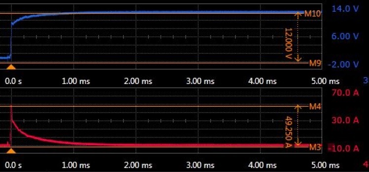
Then I found large current "about 50A" occurred...

(please refer to the picture attached. Blue is input voltage, red is input current.)

I don't know the torelance of input inrusch current on TPS62147.

Is it capable for TPS62147? Or should I reduce the current?

Thanks at advance

Edgard

  • Edgard,

    The switch current is limited to about 1.7 A typical for TPS62147.  Where and how are you measuring the inrush current?  Do you have a large bank of electrolytic capacitors on the input?

  • Dear John,

    thanks for your replying.

    I measured the inrush current at the point of VIN with a current probe. (EN is shorted to VIN)

    I attached the wire in order to measure the current from VIN to a +12V power source.

    Some capacitors are placed at the VIN, the total is 360uF.

    Is it necessary to prevent large inrush current? If so, how large is the limit current? 1.7A?

    Kindest Regards

    Edgard

  • Could anybody answer my question?

  • Edgard,

    Most likely the inrush current is only going into the input capacitors.  It is not passing thru the TPS62147 to your load.  I once worked on a military project where we were required to limit this type current.  Electrolytic capacitors appear as very low impedance when the applied voltage is zero.  This can cause large inrush current when an input voltage is initially applied.  We used a series resistor equal to Vin / I limit with a FET in parallel.  We used a circuit to sense the voltage across the input capacitor bank and turned on the FET once the input capacitors were partially charged.  I do not remember the exact details of the circuit as it was over 25 years ago, but it should not be too difficult for you to design.

  • John Tucker,

    thanks for your comments.

    Anyway, the current does not pass trhough TPS62147 as principal, my concern has been cleared.

    Kindest Regards

    Edgard