


Hi team,
My customer use TPS43060 to design a special circuit: -24V to -15V convertor, current is 2.5A, but testing result shows one issue:
When input voltage higher than -21V, like -20V or -19V or even higher, then output current can only meet 1A, or output is not stable, and MOS driver signal will missing sometimes, if input voltage is -24V or lower than -24V, then everything works good.
SCH is below:
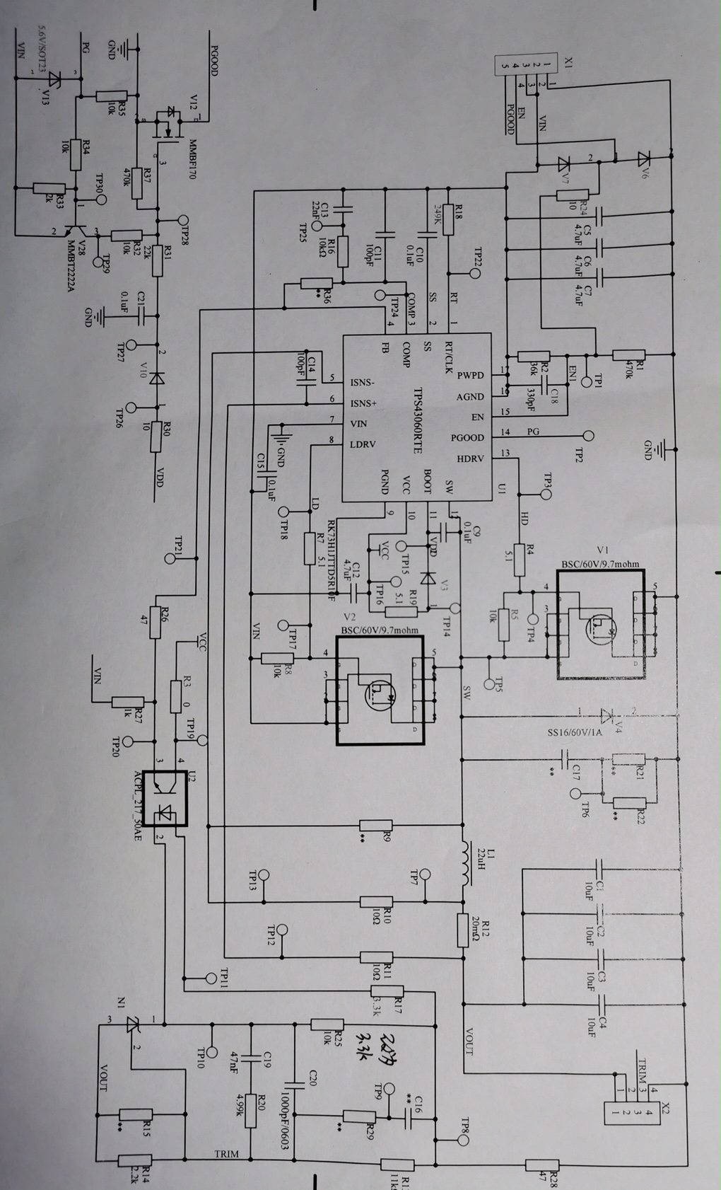
After checked with customer we found the root course, it is because of resistor between HDRV/LDVR and MOS:

When customer use 5.1ohm resistor, issue SW wave happens as below, and if input is -18V, it can only support 0.5A load at -15V output:

But if change the resistor to 10 ohm, everything become better, when input is -18V, it can only support 2.5A load at -15V output, and SW wave is quite good:

Now customer need to know why this resistor must be 10ohm rather than 5.1ohm, and if they change the resistor to 1ohm or 0ohm, issue become even worse. But our reference design shows the resistor is 0ohm, could you help to share some comments?
Thanks very much.
Regards, Sunny
