This thread has been locked.

If you have a related question, please click the "Ask a related question" button in the top right corner. The newly created question will be automatically linked to this question.

TPS22975: How to calculate "Rise Time" and "ON Delay Time" in considering Vbias

Part Number: TPS22975

Hi, Load Switch Support team,

As far as I see the 7.7 Siwtching Characteristcs of TS22975 datasheet, Vbias affects to "Vout Rise Time" and "ON Delay Time" as follows. Vbias and time appear to be inversely proportional.


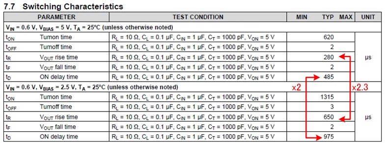
But, the Equation 1 in page 15 of TP22975 datasheet doesn't look like that Vbias is considered. And also, Table 1 is shown only the relation of Rise Time vs CT Capacitor under Vbias=5V. There is not other  table in considering Vbias is 2.5V and 3.3V.

Please clarify the equation to calculate "Rise Time" and "ON Delay Time" that considered Vbias.

By the way, is the output voltage of the internal charge pump two times of Vbias?

Regards,

Tamio

  • Hi Tamio,

    We only have equations for the rise time of the device since this is what determines the inrush current that passes through the device during turn on. Delay time and turn on time we do not have equations for. In general, you have the right idea, that VBIAS voltage and rise time are inversely proportional.

    For information on VBIAS = 3.3V calculations, you can refer to the E2E post here where equations are provided. You can also take a look at figures 19 and 20 in the TPS22975 datasheet since it shows rise time expectations across VIN and CT capacitance for VBIAS = 5V and VBIAS = 3.3V.

    Let me know if this helps with your application calculations.

    Thanks,

    Alek Kaknevicius

  • Hi, Alek,

    I confirmed other E2E sread introduced by you. That is very helpful for me. I would like to understand the relation of temperature and VBIAS, then to consider the equation. To create the equation in considering temperature, I need the data like Figure.19 and Figure.20 that measured under setting VBIAS to other voltage except 5V and 2.5V. Could you provide it to me?

    Thanks

    Tamio

  • Hi Tamio,

    Apologies for the delay here.

    We do not have the temperature data to create the graphs similar to Figure 19 and Figure 20 for VBIAS = 3.3V. However, you can use the percentage shifts in these graphs to estimate the temperature shift at VBIAS=3.3V. For example, at VBIAS=VIN=2.5V, the data can be estimated as follows:

    -40C: 2575us (+17%)

    25C: 2200us

    85C: 2000us (-9.1%)

    This means that for VBIAS=3.3V and VIN = 2.5V, the above percentages can be used to estimate up to 85C or down to -40C.

    Thanks,

    Alek Kaknevicius