This thread has been locked.

If you have a related question, please click the "Ask a related question" button in the top right corner. The newly created question will be automatically linked to this question.

BQ24192: Battery charger stopping charging

Part Number: BQ24192
Other Parts Discussed in Thread: BQSTUDIO, BQ27542-G1,

Hi team,

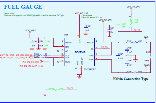
I am using bqstudio for fuel gauge calibration.

 The situation is,

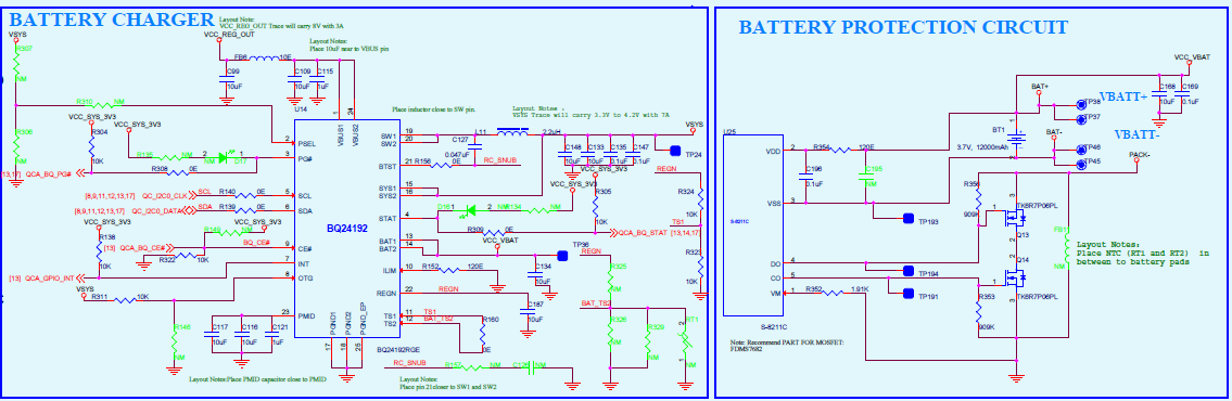
When battery voltage is in the range of 3.0v to 3.3v(Actual batt V) battery charger stopping charging .

The observation is once connecting the adapter for charging, at that time battery charger detecting max threshold(e.g. 4200mV) and stopping charging.

I have used on chip battery protection circuit for protection.

I am not understanding  why charger detecting max threshold voltage even though actual battery voltage is in 3.0v to 3.3v?

 As per TI note, battery charger suppose to turn on charging cycle if voltage goes below higher threshold voltage.

We tried to disable charging (max voltage) disable but no any effect in  charging.  

Even fuel gauge(Bq27542-G1) also detecting max voltage when battery voltage is in 3.0-3.3v.

let me know how to solve this issue ?

  • Hi,

    Looping in gauge expert to support your question.

    Thanks,

    Ning.

  • Hi ning,

    We are already doing in discussing with Andy and Kang .

    This is battery charger related problem.

    I hope u understand my concern

    Thanks

    Vishal

  • Vishal,

    Could you please provide more details?

    1. What are the test conditions such as VBUS, VBAT, IBAT, VSYS, ISYS when the behavior happens?

    2. What are all the register values when the behavior happens?

    3. If the battery protection circuit & the gauge are disconnected, and the charger is connected to charge the battery directly, will the behavior happen?

    Thanks,

    Ning. 

  • Hi Vishal,

    What's your setup like? Are you using EVMs for both charger and gauge or did you design your own? How did you connect the battery to the EVM or PCB? What's you charge current?

    I suspect the wiring used to connect the cell/battery to the gauge has high series resistance, so based on the charge current and ohms law to 4200mV is observed at the gauge and charger voltage measurement node causing the charger to turn off to prevent over charging/ over voltage of the cell.

    (4.2 -3.3)/Charging current = wiring series total series resistance.

    BQ27542-G1 doesn't have protection/protection FET control or charger control, so it can't stop charging, but the fact that they are both seeing the same voltage points excessive series resistance in wiring. Try capturing the voltage at the charger terminal when the charger stops charging.

    WHat on chip battery protection circuit are you using? Are you sure the charge current isn't causing the protection circuit to trip?

  • Hi Damian,

    Thanks for your reply.

    Yes, we are using on board battery protection circuit,gauge and battery charger.

    here i am attaching the screen shot of the same 

     Please let me know you find anything wrong if you found.

    Just FYI I have disconnected the all the above three section, I have used only charger for charging and that is happening .

    Thanks

    vishal


  • Hi Ning,

    I have isolated and working fine and battery charging well.

    Here is my observation.

    1.When charging is not happening in the above mentioned range at that time BATFET is in ON condition and  voltage on SYS and BAT pin is what voltage present on  battery.

    2.But According logs battery is not charging and discharging.

    3.Once the voltage reach to/above the 3.3v then it will start fast charging. can you explain me what battery charger detecting high threshold voltage?

    Beside,

    We are doing the satellite connection for that we need 3.0amps current when battery voltage comes 3.477v our system is stopping.

    Can you please tell me why this is happening? 

  • Hi Ning,

    Now  now my circuit is battery charger with fuel gauge.

    In this, say my voltage is in the range 3.0v-3.3v and my charging is not happening?

    Please advice.

    This is very critical for us.

    Thanks,

    vishal

  • Vishay,

    Could you please clarify the followings?

    1. If the charger is connected to the battery directly, it can charge normally when VBAT is 3.0v-3.3v. Is it right?

    2. If the charger is connected to the battery via gauge, it does NOT charge when VBAT is 3.0v-3.3v. Is it right?

    Thanks,

    Ning.

  • Hi Ning,

    Yes, you are correct.

  • Hi Ning,

    I am waiting your reply as soon as possible.

    FYI we already spent around 1 month to carry out the successful learning cycle and we are facing charging issue.

    Already attached screenshot of the following ckt.

    1.Battery charger 

    2. fuel gauge 

    3.battery protection ckt.

    Please let us know your view on the above issue.

    Awaiting your soonest response ?

    Thanks 

    vishal

  • Hi Vishal,

    I believe the issue is your Battery Protection IC S-8211C, charger and Fuel gauge grounds are incorrect. This is the source of the issue. Fuel gauge VSS should be BAT- as well as it's components ground reference. Charger ground connection should be CHG FET source, which it is correct but should be PACK-. SRN should be connected to source of the DSG FET as it currently, but node should be renamed. 

  • Hi Damian,

    Thanks for the reply.

    I will look into this and update you.

    Thanks 

    vishal

  • Hi Damian,

    If  ground  issue is there why its charging after 3.3V? Why not below that?

    I did what you have told in above reply.

    But still charging is not happening, getting the result same as earlier.

    According to charging profile, if the battery is in the range of 2.0-3.0v it should be charge in pre-charge  mode .R8?

    I am attaching the battery protection IC pdf.

    Please do the needful

    S8211C_E.pdf

  • Vishal,

    The feedback I provided is what I could help with. Please work with Ning or Battery protection IC support to figure out the issue with charging. The battery gauge doesn't prevent or inhibit charging, it only reports battery conditions it measures. The two ICs with the capability of stopping charging is charger and the battery protection IC. You've mentioned you can charge when the charger is connected directly to the battery, so it looks like the culprit maybe the battery protection IC.  When charging stops or is prevented, have you checked the state of the CO and DO pins? If you bypass the protection FETs (short across them) does charging and gauging function as expected? Please try these debug and let us know, so we can better assist you. 

  • Hi Vishal,

    I reviewed your battery protection IC spec and your schematic. I'm very confident that the battery protection IC is what's preventing charging due to the charge overcurrent. The protection IC uses the RDSon of the DSG and CHG FET and the voltage across them to detect charge overcurrent condition. Based on your connections with the gauge you've also included voltage across the gauge 10m-Ohm current sense resistor into battery protection IC charge overcurrent voltage measurement, which is between VSS and VM. In order to resolve this issue the battery protection IC VSS should be connected your PACK-. You also have a bunch of other ground referencing issue on the gauge side, which would impact gauging and gauging accuracy. PLEASE NOTE the gauge IC ground reference should be BAT-.

  • Hi Damian,

    Thanks for the reply.

    When charging stops charging FET is turned off and discharging FET is in ON condition

    Status of DO=voltage across the battery(3.0) (gate of the Discharge FET)

    Staus of CO=0V(gate of the Charge FET)

    If you bypass the protection FETs (short across them) does charging and gauging function as expected?-----Yes charging starts.I have bypassed the FET and tried.

    Please let me know your feedback on the same 

    Thanks,

    vishal

  • Hi Damian,

     In order to resolve this issue the battery protection IC VSS should be connected your PACK-.     -------------------------------------

    If i do VSS connect with PACK-, what is the use of sense resistor which is used in between BATT- and PACK-.?

    PLEASE NOTE the gauge IC ground reference should be BAT-.   -------------------------------------------

    yes sure that we have done already 

  • The sense resistor between BATT- and PACK- is used by the gauge for coulomb counting and current measurements. It's not needed by the protection circuit.

  • Hi Damian,

    we will check at morning and let you know the result.

    Thanks,

    Vishal

  • Hi Damian,

    What i did is i have cut the trace which is going between Vbatt- and VSS pin of the protection ic.

    So i have connected Source of the lower (Charge mosfet) which is actual pack- to the VSS.

    in this VM and VSS pins having same ground references. so according to protection IC datasheet charging and discharging action will happen wrt to voltage diff between VM and VSS pin. 

    In this case charging was started but it will not protect the battery.

  • In above battaery is charging but not geeting path for discharging .

    Please help here to solve above situation.

  • Vishal,

    If the BAT1/BAT2 pin voltage to ground seen by BQ24192 is different from the real battery pack terminal voltages, there's little the charger may do. Please check with Battery Protection IC S-8211C support as suggested.

    Thanks,

    Ning.