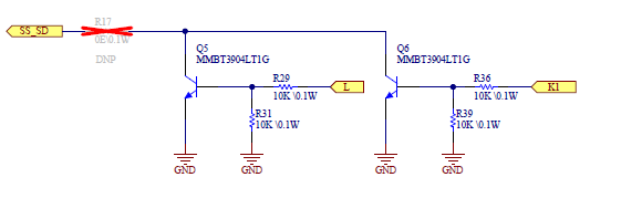
I am using the UCC2897A chip to generate 12V from 80-120V input. I want to switch off the gate signals in case of over current, short circuit and other faults. Currently, I am trying to use the given circuit(As soon as L or K1 will go high, I want my chip to shut down) at the SS/SD pin of the chip to control its output. But as soon as I am connecting this circuit(given below), my output will fall from 12V to lower voltage as I will connect some load at the output. But if I am not connecting the R17 resister my circuit is working fine at all loads. I am not able to understand why this is happening. Is there any other way in which I can control the chip? Please suggest some ways in which I can overcome this issue.
Note: - K1 and L are the outputs of the logic gates CD4072BM96 and CD4001UBM96 respectively.