This thread has been locked.

If you have a related question, please click the "Ask a related question" button in the top right corner. The newly created question will be automatically linked to this question.

TPS53355: TPS53355

Part Number: TPS53355

I have this part on two new designs and the 12VDC input has very large voltage spikes when i turn on this regulator. the output from this (1.02VDC) look good and quiet.

I have more than enough input and output capacitance which are a mixture of ceramic, Polymer, Tantalum and alum types trying to calm this down. 

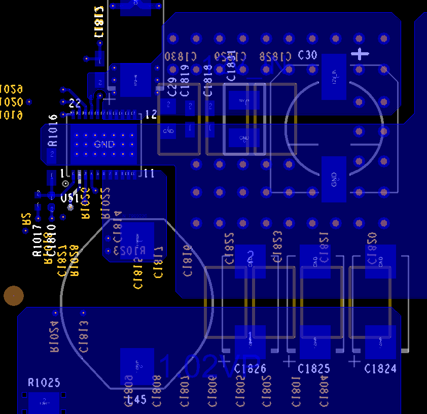
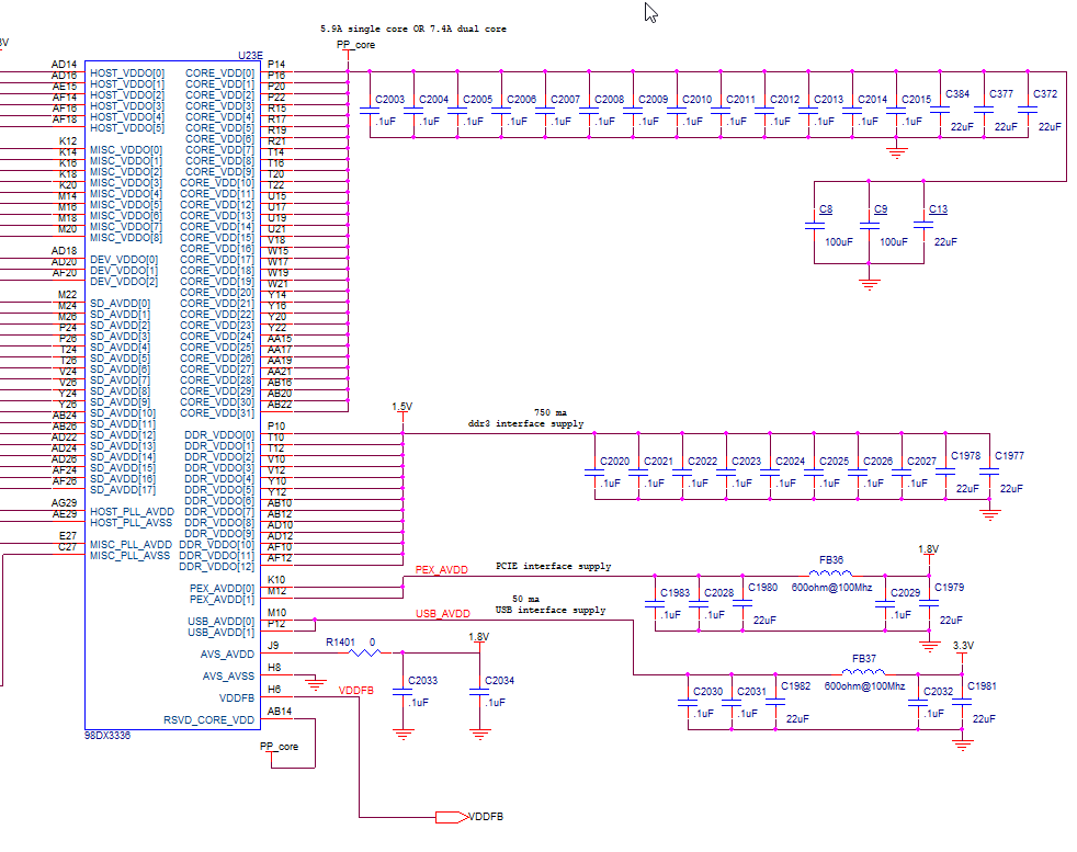
Can i get some help on this? I can supply the schematic, layout and BOM for the circuit. this part is trickier than any other regulator i have used so i could use some help with some of the math equations i see in the datasheet. maybe R7 needs to be modified in your figure 38 on the datasheet?

I really stuck right now so if you could get back to me quickly that would be best for me.

Brad 

  • Hi Brad,

    I noticed you have the resistor on the Trip pin set to 82.5 kohms, which would give you a current limit around 20.4A. Based on the requirements in your schematic, I would recommend using roughly a 116 kohm resistor instead, although to test to see if this fixes your issue you can try installing a 147 kohm resistor which should set the current limit far higher than the 25A you have listed in your schematic. Let me know if changing this resistor fixes you issue.

    Best regards,

    Layne J

  • actually I'm not drawing any where near 20A's. In this design it closer to say 7.5A max. in another design it will be closer to 22A max. How will changing this effect the input ripple this is causing?  I see at least .5vpp noise  spikes on the 12v input. both designs do the same exact thing where the 12v input is just getting punished.

    brad

     I actually re-designed the layout as I thought I had too much inductance in the power entry into this regulator. I have some solid ground and power planes now with tons of feed thru stitching and it made no difference at all.  I believe it's a fantastic layout myself but I could share it with you.

    I was thinking "maybe" R1023 needs to be adjusted??   (I just tried this going to 10K .... made no difference in input noise). I know it's from this regulator as if i disconnect the output from the regulator the input noise spikes go away.

    and one more thing, the current numbers are from worst case datasheets and i measure about 1/2 of what I stated above.

  • Hi Brad,

    Can you attach a waveform of the input supply when you are seeing this issue? Also, when you are seeing this issue how are you connecting the scope probes to the board? I would recommend using the tip and barrel method and measuring across the input capacitor closest to the TPS53355 IC. See page 6 of the TPS53355 EVM User's Guide for more information on this.

    I have also attached a calculator file to help calculator the components your design will require. Please go through this to ensure your design meets the minimum requirements.

    6471.TPS5335x_Calculator_Checklist.xlsx

    Best regards,

    Layne J

  • I use the tip and spring at the end of the scope so I get a great short ground. I go right across the capacitor the one closest to the regulator. 

    let me capture the waveform and send it.  wave form.pdf6371.SCH.pdf

  • I don't know if you got these as i pasted them into the older thread. 

    here is the top side of the layout. there are separate ground and 12VDC input power planes too. 

    the wave form is directly on C29 and I use the spring clip attached the end of the probe for very good fidelity.

    I use a mix of input acapacitor types trying to get this input spikes to go away. ceramic, tant and polymer.

    on the output I use mostly ceramic (10 -10uF , 2 - 47uF, 2 - 100uF) and 3 - 330uF tants

    could it be the equivalent series resistance on the out put is too low?   of course where the output is delivered to the switch chip there are more ceramic decoupling caps. ( see attached) below)

    I have tried to adjust R1023 to 10K with no change on the input wave form.

     0131.SCH.pdf5756.wave form.pdf

  • Hi Brad,

    It looks like the spikes you are seeing in the waveform is related to the switching of the part. I would recommend adding some input capacitors to filter out the high frequency noise. I would recommend trying a 0.1 uF cap and maybe a 1 uF cap as well and then check to see if you are still seeing this noise.

    Best regards,

    Layne J

  • I have tried adding caps and it does not change the issue. I have two .1uF right on the input pins. (see below) input caps.pdf

    I also have a different POL i can switch to on this board. if i disconnect the out of this one and enable the other the noise goes away. the issue with that one is i cant use the feed back loop Marvell needs to satisfy the switching chip core voltage adjustment they require. 

  • it did help a bit. let me play around with some different values.

    I will let you know.

    thanks,

    brad