This thread has been locked.

If you have a related question, please click the "Ask a related question" button in the top right corner. The newly created question will be automatically linked to this question.

TPS61500: TPS61500 Backlight jitter at 200Hz, 6% duty cycle

Part Number: TPS61500

HI,

1,Backlight jitter at 200Hz, 6% duty cycle.

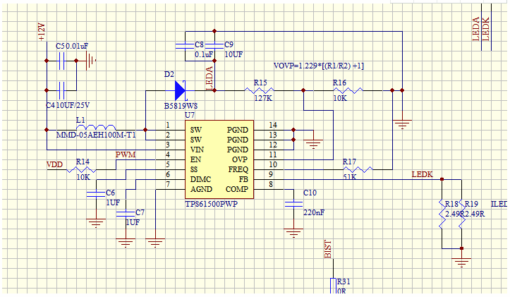
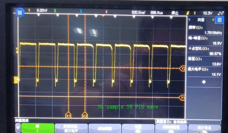
2,Raise the original input voltage from 12V to 14V. At this time, the wave form of the normal pin SW pin pin pin has become straight (because the backlight voltage has been reached), but the wave form of the defective product remains the same

3,Change the resistance of setting the switch frequency from(R17) 51K ohm to 90K ohm. At this time, the defective products are normal and the waveform measurement is normal. However, the different frequency has a great impact on the customer, so it is difficult for the customer to verify again;Please confirm whether our schematic design is OK as shown below?

Thanks

  • Hi Sir,

        For such kind of application, I don't think you need such 2Mhz switching frequency, But I suggest testing when the switching frequency 2Mhz, you can try with 4.7uH inductor. 

       BTW, what's the LED configuration? How about the output voltage?

       I think you can change the different switching frequency based on the efficiency since high switching frequency will cause high switching loss, you'd better balance the switching frequency and power loss.

    BR

    Sean

  • We use 3.9UH inductor to test (there is no 4.7UH on hand for the time being), it does not work, or the same bad phenomenon as before;

    Originally we used the following models:

    The following is our product backlight parameters

    At present, we have mass production orders, based on the current situation, how should we analyze and ensure production?

  • We use 3.9UH inductor to test (there is no 4.7UH on hand for the time being),  the same bad phenomenon as before;

    Originally we used the following models:

    The following is our product backlight parameters

    At present, we have mass production orders, based on the current situation, how should we analyze and ensure production?

  • Hi Sir,

        From your description, it seems the control loop is not very stable with 2MHz, and you can also try to increase the C10 from 220nF to 470nF or 680nF.  It can help to narrow the bandwidth and help to stabilize the control loop.

       Another point is that your OVP point is a little low, you 'd better set it higher. 

    BR

    Sean

  • dear:

    I have just used 470 nf to measure the C10 capacitance and still haven't solved the problem.

    Before I also tried to use 1 UF, also did not solve the problem; 

    2.Change the resistance to set the switching frequency from the original 51K ohm to 90K ohm, at this time the bad product is normal, what is the reason?

  •  

    dear :

    we Hope to get your reply,thanks

  • Hi Sir,

        I don't have much more commons here, what you can do is to change the switching frequency, it seems for high switching frequency it is not very stable. So what's the problem if you use the lower switching frequency?

  • Hi Sir,

    The original 51 Kohm changed to 90 Kohm after the product is normal, but logical how to explain the problem to the customer?

    we need to report to customer, hope to get your reply, thanks. 

  • Hi Sir,

         The only reason that I guessed is the loop maybe not very stable under such high switching frequency.

  • hi

    Now our previous production of 300pcs have 2pcs have such bad, reduce the switching frequency in the logic can avoid similar problems?

  • Hi Sir,

        Yes, actually I don't think your previous design need suck kind of high switching frequency.

    BR

    Sean

  • hi sir

    1. now i change the resistance of the frequency to 91 K (switching frequency is 1.14 MHZ), at this time the PWM is 200 duty cycle, the inductor has a slight sound, then i change the C10 to have the original 220 nf to 100 this time the sound disappeared; may i know if such a scheme is ok?

    2.How does the capacitor C10 work? Could you explain it with a simple diagram; it's a little unclear about the loop;

  • Hi Sir,

        Since you have decreased the C10 value, it will get the wider bandwidth.

         C10 is connected to the output of the internal error amplifier, and this cap provides zero and pole for the control loop that helps the loop stable. It is a very common structure where you can find this structure from a  lot of devices' block diagram.

    BR

    Sean