This thread has been locked.

If you have a related question, please click the "Ask a related question" button in the top right corner. The newly created question will be automatically linked to this question.

LM27762: Strange behavior from LM27762

Part Number: LM27762

hello everyone,

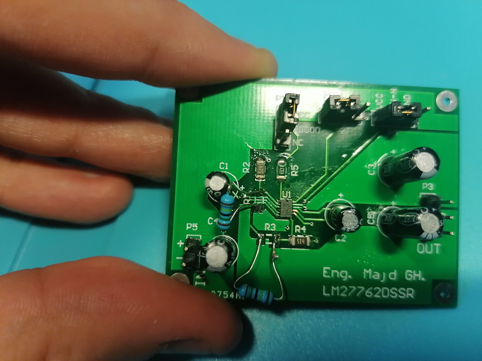
i was trying to make some testing on LM27762 before i use it in other projects.

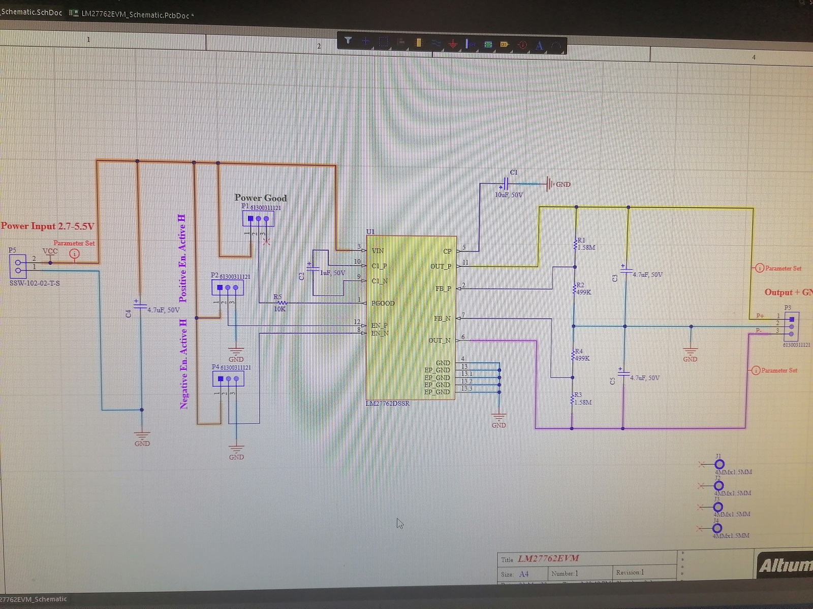
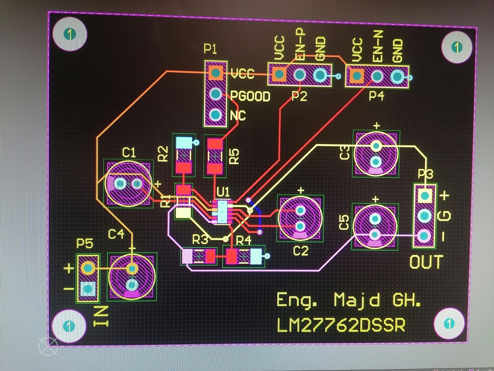
so i made a pcb with Altium and designed the schematic based on the values from Texas Instruments site using WEBENCH so the voltage divider were 499K and 1.58M because i wanted to have +5 and - 5 from 5.5 Power..

anyway i made the circuit and tested it and i got from the positive output the same voltage from as input and from the negative output always - 3.8 as Minimum

the value of negative output is more positive like - 3 when i reduce the input voltage and the output of positive output is always the same as input.

now i replaced the chip because i thought it might be damaged or so, but i got the same results.

can someone helps me. Thanks in Advance.

  • Hello Majd,

    Can you please share the schematic diagram and layout so I can check it? If you are not comfortable sharing it here, then I can send an email.

    Thank you.

    Best regards,

    Excel

  • Hello,

    can you send me a schematic and can you give more info about your application Vin, Vout and the load for the positive and negative rails?

  • Hello thanks for your reply,

    these are the photos, and as a notice i used 1.5M resistor because i don't have right now 1.58. and this is only a test and when i see that this IC can work with my projekt i planned to change the components to 0805 or and put the caps on the bottom layer.

    I forgot to say that the Enable + and - is working correctly but the problem that described above is still exist.

  • I still didn't use any load on the output.. because i still see a problem with the output.. negative voltage is not correct and positive, negative voltage is not regulated

  • hello

    until now i didn't discover the solution. I checked all tracks an connectivity under microscope but it seems all is correct.. No short and all pins are connected with each other, i bought the 2 Chips from Mouser, could it be that both are damaged?

    because even the positive rail has always exactly the same input voltage.

  • The capacitors must be ceramic. Electrolytic capacitors have too much ESR.

    Please read section 10 of the datasheet; all those guidelines need to be followed.

  • okay thanks for reply. i would re design the circuit and order all Ceramic Capacitors. i also would buy new LM27762 chips to test with the new board. 

    but i need jetzt sometime.. i would post the results in the future. 

    anyway i didn't take these rules into consideration because that was a quick test and i didn't thought at this too low oscillating frequency that this going to cause this Problem, because i sometime make circuits that works upto 100 MHz on breadboard. Thanks