This thread has been locked.

If you have a related question, please click the "Ask a related question" button in the top right corner. The newly created question will be automatically linked to this question.

TPS61099: Low load for the TPS61099

Part Number: TPS61099

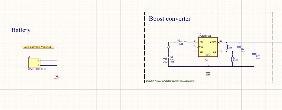
We are using the TPS61099 chip to power our ultra low power electronics and are experiencing a current load we do not understand.

We are testing our electronics is sleep mode and are seeing a current pull we do not understand.

As a results we have tested the circuit(both the EVM board and our actual electronics.

We have placed a 10K Ohm load on the TPS61099 and expect to see an average current pull of 0.12mA, (we are using a 1.2v power source).

We are actually recording a current pull of a maximum of 4.913 mA every 2.4342 milliseconds.

Can you please explain why the current is so high and has a average of 277mA compared with 0.12mA.

Thank you

  • PS I should have mentioned we are measuring the current pull at the Vin (NOT Vout).

    And the current pull of 0.277mA NOT 277mA

  • Hi Norman:

    I guess it's caused by the burst mode(PFM). May you measure the SW waveform to double check it?

  • I have attached the waveform that we are seeing as the current pull.

    As you can see from the waveform measured at input to the TPS61099 and load 10K Ohm load on Vout,  we are seeing much larger than expected current pulls. Up to 5-7mA with an average of over 0.277mA.

    These current pull are depleting the battery much faster than expected.

    We cannot see from the datasheets or otherwise where the current pulls originate from. Especially, as we would expect a current of 0.12mA for a 10K ohm load.

    We urgently need help with this issue.

    Thank you.

  • Hi Norman:

    The current pulse looks like the Burst mode. If the converter operats in Burst mode, it won't switch continually. There is details in datasheet 8.3.1 as "If the load current is reduced further, the boost converter enters into Burst mode. In Burst mode, the boost converter ramps up the output voltage with several switching cycles. Once the output voltage exceeds a setting threshold, the device stops switching and goes into a sleep status. In sleep status, the device consumes less quiescent current. It resumes switching when the output voltage is below the setting threshold."

    May I know what's your Vout? And why you expect 0.12mA? (I afraid you may misunderstand the operation principle of a Boost converter.)  

  • Hello,

    We are testing a production batch of PCBAs and development PCBA (Printed Circuit Board Assembled).

    Normally the production PCBAs are powered from a non-rechargeable battery pack that consists of 2x Zinc Air P675 batteries connected in parallel. Therefore the input voltage is normally in the range of 1.3 to 0.8v depending on the discharge of the batteries. The electronics runs off a Vout of the TPS61099YFF, a 1.8 Vout.

    We are measuring the production and development PCBA using a power profiler. To confirm the power profiler accuracy we are connecting with a output voltage of 1.2v across different loads. 100 Ohms, 1,000 Ohms, 10,000 Ohms, 100,000Ohms and 1,000,0000Ohms with the resulting power profiles of 12.5398mA, 1.2285mA, 0.1234mA, 0.0152mA and 0.0036mA respectively.

    When we placed the load of 10,000 Ohms across the Vout of the TPS61099YFF we are measuring the power profile in mA shown in the attached diagram at the Vin of the TPS61099YFF. In other works we are measuring a peak mA of 6-7mA every 2.342ms with an average mA current of 0.227mA at the Vin of the TPS61099YFF.

    We need to understand why the measured input current of the TPS61099YFF can be up to 6-7mA for a 2.342ms with an average of 0.227 mA. The power requirements are much higher than we would expect.

    Is there a pin compatible version of another chip we can swap the existing TPS61099YFF for?

  • As an FYI below is the circuit diagram of the TPS6099YFF in use.

  • Hi Norman:

    The Iin_avg=Vo*Io/Vin/Efficiency. And if the load is so light, with Vout =1.8V, it's normal to see Effiency lower than 80%. (So even efficiency=100%, the iin=0.12mA you expected is unavailable to achieve with such conditions.)

    The pulse you observed is caused by Burst mode. It will switch once and wait some time for the next pulse. This behavior reduces the switching loss with light load. If you don't like that, you could add an input filter to decrease the current spike.

  • Hi,

    In the reply you mentioned an input filter that can decrease the current spike. Do you have a sample design of such an input filter?

    Also I asked about a pin compatible alternative to the TPS61099YFF. Please mention the alternatives in your reply.

  • Hi Norman:

    An LC filter or just enlarge the input capacitance could help to decrease the spike.

    The burst mode(PFM mode) is necessary to reduce the switching loss. It's a normal phenomenon for this topology, and not only for TPS61099. And for the efficiency, it's also good with such low voltage and light load. I'm willing to recommend better solution, but till now, TPS61099 is suitable for this case. If you have additional concern, please let me know and check if there is a good alternative part. 

  • Hi Norman:

    Besides, did you do efficiency calculation? If you have, it's better to share the details with me, I could check if we have any gap about the number.

  • We presently use the recommended input capacitor of 10uF. Can you tell us what input capacitor to use? The value and type of capacitor would be good.

    We can increase the capacitor to 22uF without scrapping the 500+ production PCBs we have.

    With regards to the average input current to get the equation to match the input current measurements we are  setting we have to put an efficiency for 100% into the equation. So the input current measurements match the expected results.

    Using the provided equation of   Iin_avg=Vo*Io/Vin/Efficiency and a 10K fixed load we get where

    Vo = 1.8volts, Io = 0.18mA (using the 10K fixed load),  Vin = 1.2 volts we have to adjust the efficiency to 100% to get the measured output. An efficiency that is not possible according to the email.

    Please recommend a pin compatible alternative to the TPS61099. We can test the pin compatible alternative as the same time.

  • Hi Norman:

    Do you have special requirement to limit the current spike? If not, then 10uF is OK.

    The converter can't reach 100% Efficiency. Efficiency =Vout*Io/Vin/Iin=1.8V*0.18mA/1.2V/0.227mA>100%. I afraid there is measurement error. And typically, the efficiency is around 85% for such condition. 

  • Hi Norman:

    Additionally, I checked with team, there is no suitable alternative part for TPS61099.