This thread has been locked.

If you have a related question, please click the "Ask a related question" button in the top right corner. The newly created question will be automatically linked to this question.

BQ25150: BQ25150:The power supply of single battery is abnormal!VDD without output.

Part Number: BQ25150
Other Parts Discussed in Thread: BQSTUDIO, TPS65631W, BQ25155, EV2400

Hello:

Currently, when debugging BQ25150, I encountered two problems as follows:

1.Most of the time, the PMID foot will output the voltage value close to the VBUS. Use bqstudio to change the ICHG_CTRL and ILIMCTRL values.The PMID was restored to around VBAT+ 0.2v。

Q: why is the VBUS voltage output?Why does changing both values affect PMID?

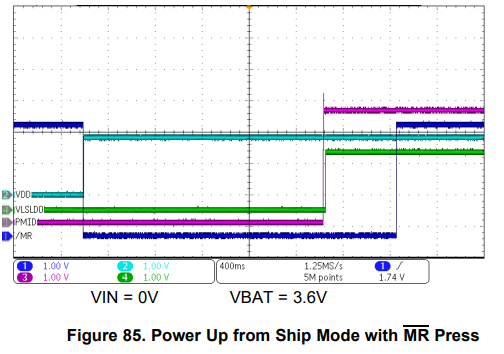
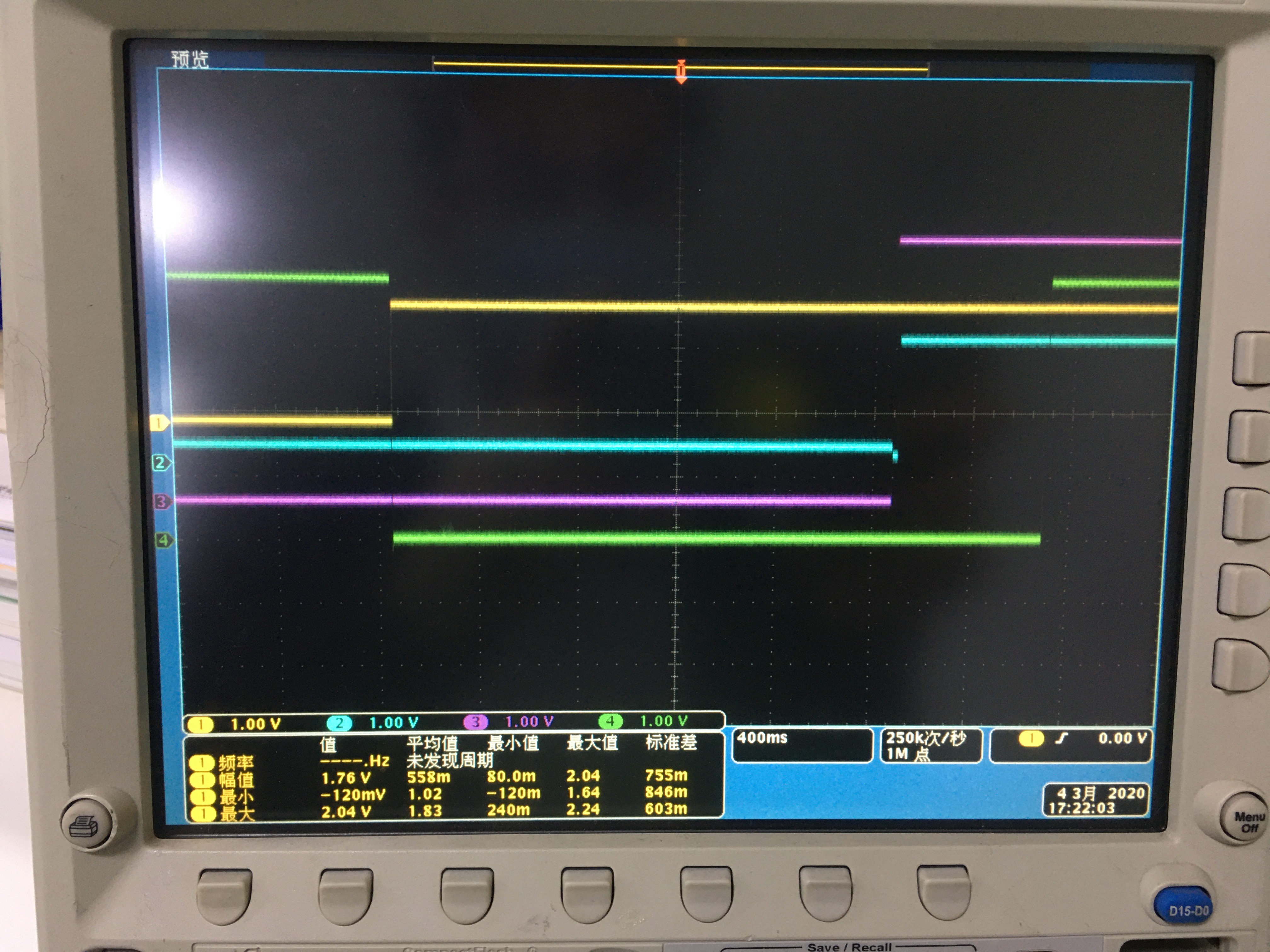
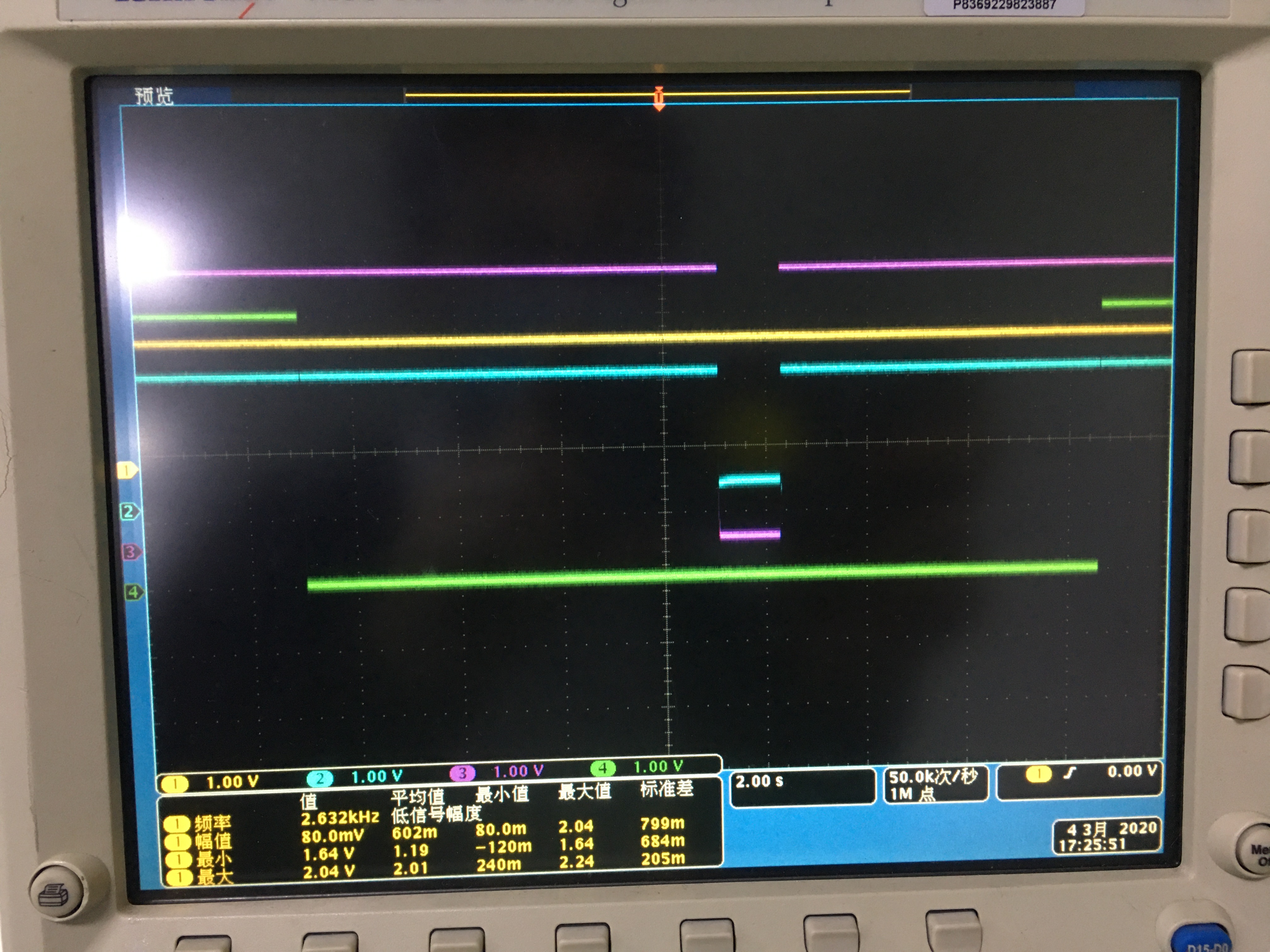
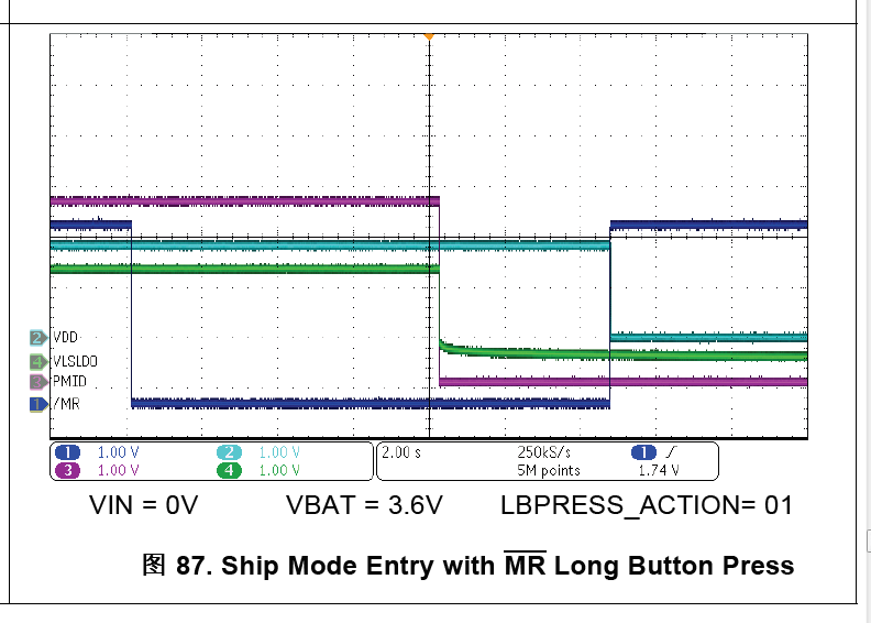
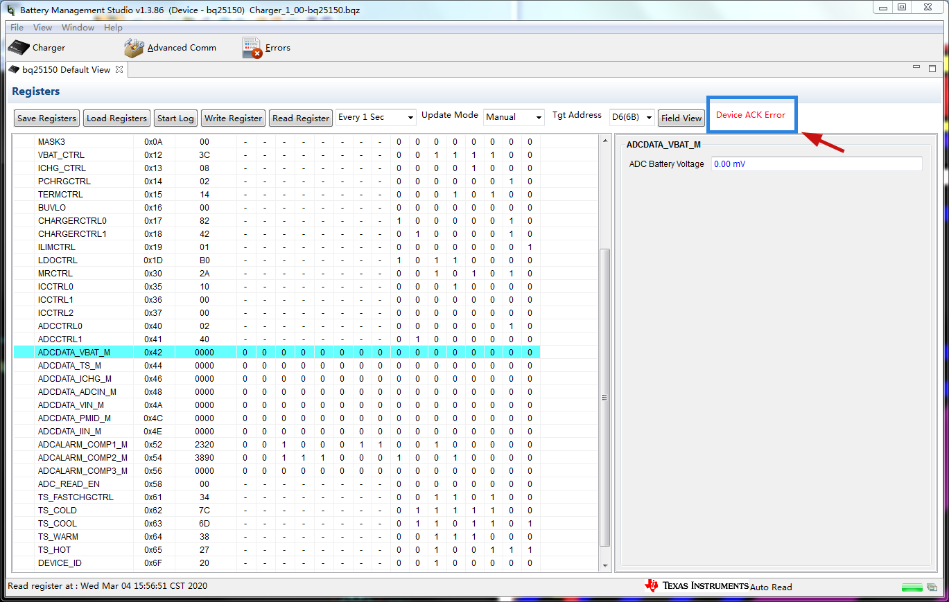
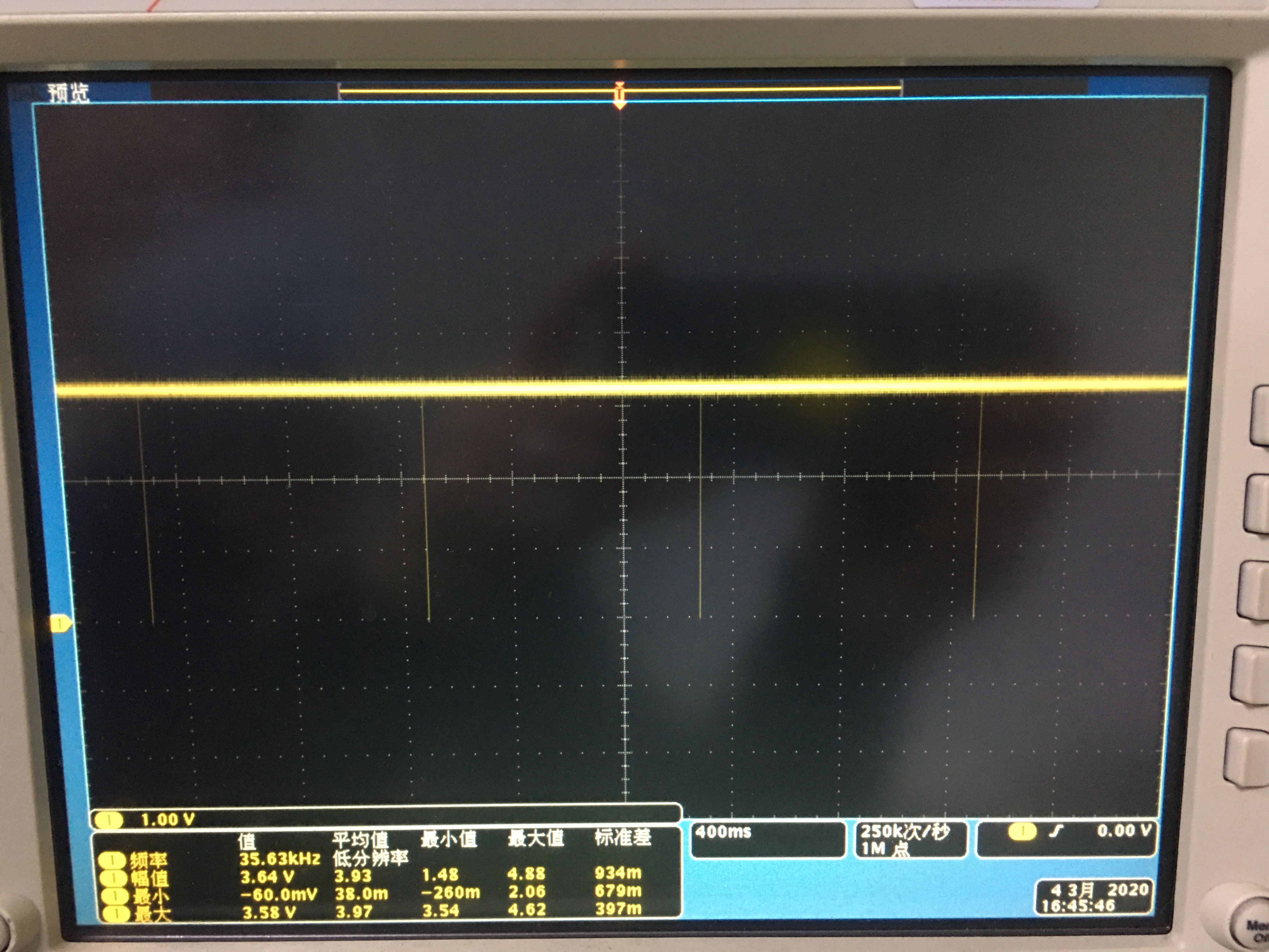
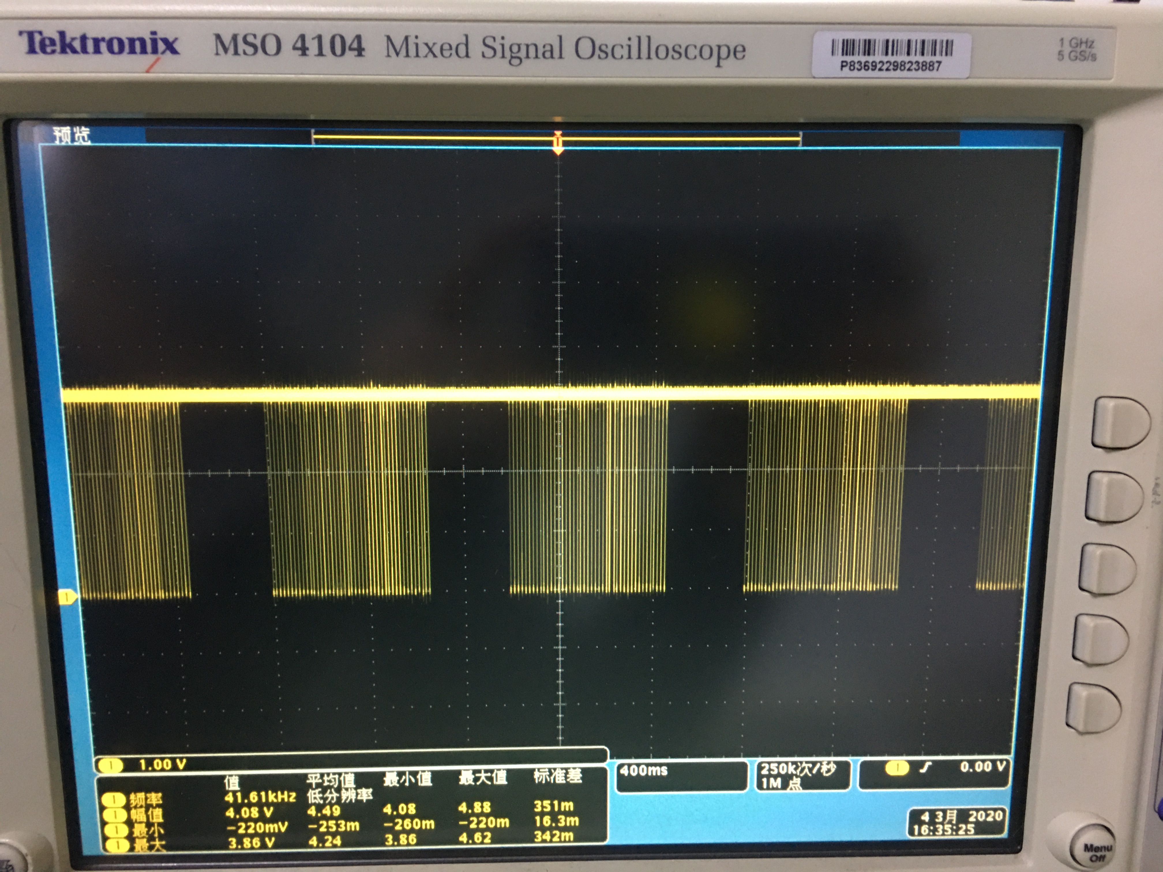
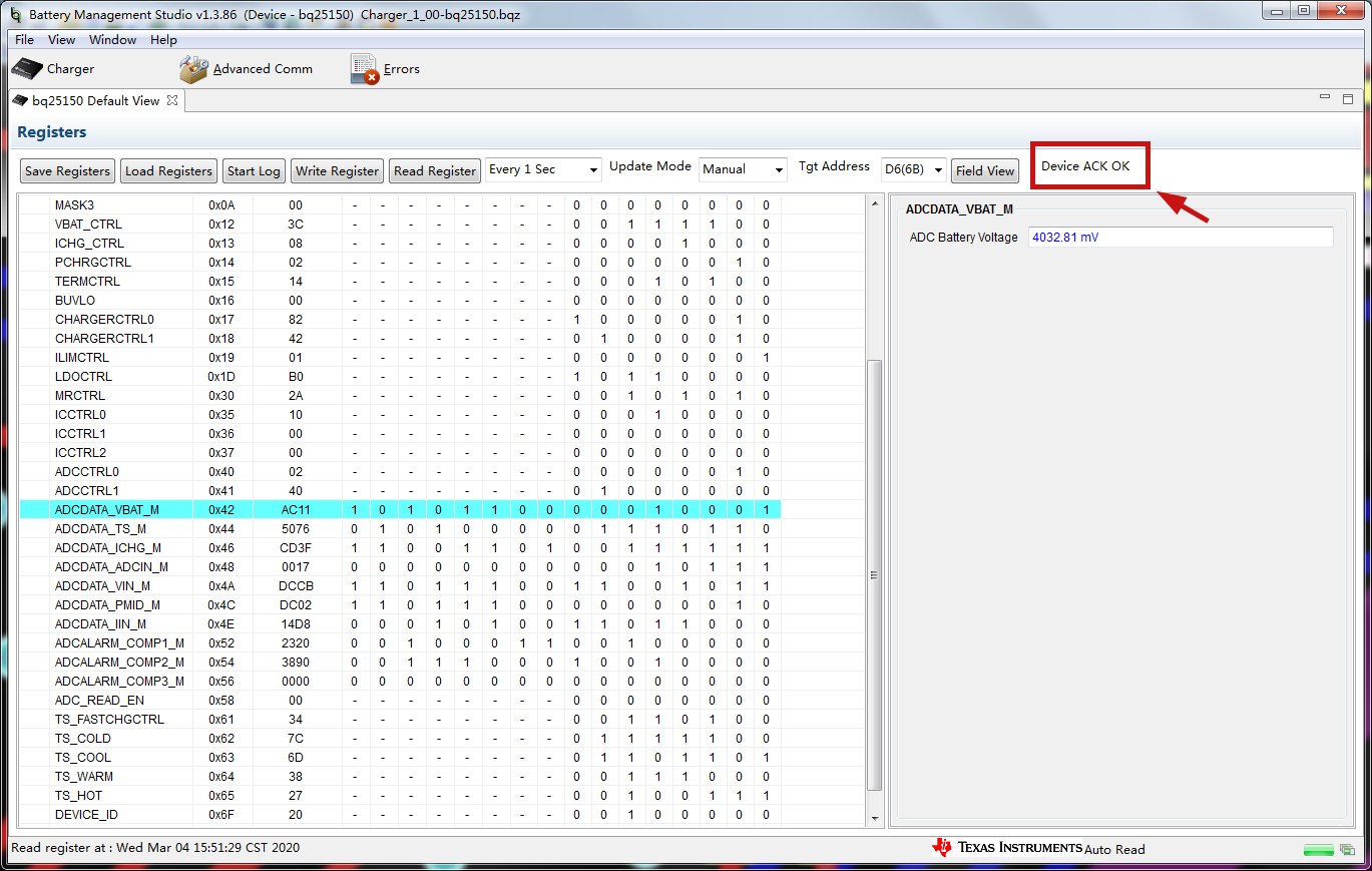
2.VDD, LDO and PMID are not output each time the battery is separately inserted, and I2C cannot communicate.Must insert the USB to restore normal, again unplug the USB is still normal。

Q: why does this happen?How do I operate the external configuration to power the battery alone?

Thank you very much.

YiTian.

  • Hello Yitian,

    1. On the PMID voltage dropping, Is the adapter able to supply the ILIM current? This indicates that the load on PMID is very high and the PMID is dropping as the DPPM loop throttles the charging. What load do you have on PMID? Can you share a register dump when this happens to see what faults could be triggered?

    2. The device will wake up and go to shipmode on battery insertion. If you hold the /MR pushbutton low or the adapter is connected, the device will wake up from shipmode. The button has to be held for 2s to wake up the device. Let us know if you have any questions. 

    Regards,

    Gautham

  • Hello Gautham,

    1.The output capacity of the adapter we used was 5V/ 2.4a, BQ25150 for initial configuration, ILIM=100mA, ICHG=10mA.The PMID output may reach the VBUS value, which would exceed the maximum input of the AMOLED power supply (TPS65631W) behind us.Want to know why PMID outputs high voltage at light load instead of VBAT+ 0.2v?How to avoid PMID output close to VBUS?

    2.Yes, we want the BQ25150 to go into normal mode as soon as the battery is plugged in.The /MR button is suspended and the adapter is not connected. At this time, the PMID, VDD and LDO of the inserted battery have no output, and I2C cannot communicate, which is an undesirable result.When /MR is pressed for a few seconds, VDD outputs 1.8v, which can be recognized by I2C.However, PMID and LDO are still not output.What should I do?The PMID powers SYS.

    Regards,

    YiTian

  • Hello YiTian,

    1. On the BQ25150- the VBUS to VPMID is not regulated- if you are looking for regulation, I would recommend the BQ25155 which has the regulation function enabled and you can select the voltage on PMID. On the BQ25150- the VIN to PMID is pretty much functional as a switch with current limit. (attached image of BQ25155 settings)

    2. Do you have a scope capture of this behavior- did you hold the /MR low for 2s? VDD will come up as soon as button is pressed and after 2s, the PMID will also come up. The BQ25155 has a wake timer of 125ms compared to 2s on BQ25150. I have included both the samples on this thread for your review. 

    Let us know if you have any questions! 

    Regards,

    Gautham


  • Hello Gautham,

    1.Ok, thanks for your recommendation, we will try to use BQ25155. At the same time, please provide the file "charger_1_00-bq25155.bqz".

    2.Just try to trigger /MR pin to capture the voltage at each point, the state is correct, please see the following figure:

    However, when the /MR pin is triggered again to enter Ship Mode, the capture curve does not conform to the specification, please give the reason.The results are as follows:

    3.When only the battery is powered, the boot is triggered by /MR pin. At this time, the I2C communication error is caused by the internal use of 3.3v pull-up of EV2400, which is caused by the conflict with the 1.8v VIO of BQ25150?At present, 1.8v MCU has not been used to communicate with BQ25150 for verification.

    4. In the third question, after I inserted USB, I2C immediately returned to normal, and bqstudio could read data in real time.Unplug USB instant error, please help to analyze the reason.

    Regards,

    YiTian

  • Hello YiTian,

    1. Attached the BQ25155 BQZ file on this message. If you download the latest version of BQStudio (test version) the update should be there. You would need to dump this file on the 'config' folder of the BQStudio program. 

    2. The device on default is configured to trigger a "hardware reset"- based on the scope capture I see that occurring. If you want to go to shipmode on long press, you will need to write Reg: 0x36 (ICCTRL1) with Value: 0x80. Also if you can include markers on which color of trace is which line, that would be very helpful for diagnosis. I think Green is /MR, Pink is PMID, Blue is VDD. Let me know if this is different. 

    3. VIO can be 1.8V and SCL/SDA can pull up higher than VIO- not an issue. However, make sure the VPULLUP Jumper is disconnected as the EV2400 has pullups internal to the box. In your system, you will need to pull VIO to the same level the I2C level is pulled up to. 

    4. What is the status of the /LP pin? You will need /LP pin to be pulled up high in order to communicate to the device on battery only. 

    Let us know if you have any questions. 

    Regards,

    Gautham

    https://e2e.ti.com/cfs-file/__key/communityserver-discussions-components-files/196/Charger_5F00_1_5F00_00_2D00_bq25155.bqz

  • Hello Gautham,

    1.Thank you for providing the document. We have learned how to use it.

    2.I'm sorry that the second long press /MR waveform I captured is indeed a "hardware reset", and the specification description has been compared.We will consider whether it is necessary to use a long press to enter the ship mode function.At the same time, please forgive me for not marking the line color correspondence.Supplement: yellow is VDD, blue is LDO, pink is PMID, and green is /MR.

    3.By VPULLUP, do you mean the pull-up resistance in my design?Or is it inside the EV2400?Tried to break the system, but could not communicate with EV2400.In addition, we tried to communicate with a 1.8v MCU, which is normal.(note: the inability to communicate with EV2400 is due to separate battery insertion, which only appears after long press 2s /MR to start, but is normal after USB insertion)

    4.I have tried to connect /LP to VBAT, and the phenomenon is the same.

    5.We have three motherboards. After the first battery insertion, we tried to press 2s /MR to boot up, only VDD output 1.8v, LDO and PMID none output.Is it because of chip damage?

    Regards,

    YiTian

  • Hello YiTian,

    1. Great! 

    2.Thanks so much. It really helps. 

    3. There is a pullup jumper on the EVM(as attached). You can disconnect it if you are using the EV2400. The device seems to be in shipmode this time due to the battery insertion. Long press of 2s on /MR line or one time adapter plugin will wake up the device. 

    4. Probably still in shipmode- can you measure VPMID voltage when this happens?

    5. It might be good to see a plot of this profile- is PMID trying to come up and shuts down or someother behavior? Also a schematic can be helpful- if you want to email- I can send an email to you.  

    Regards,

    Gautham

  • Hello Gautham,

    3&4.The device has been awakened and the PMID voltage output is normal.Just now I tried to drag /LP to VBAT, while opening the internal ADC_READ_EN, which is ready to read through EV2400.So the state of /LP is the key to communication. I think we have found the answer to our question. Thank you for your help.

    5.We get the phenomenon of long press /MR wake-up, can only open VDD, PMID and LDO is not output.But there are two Boards that are normal.If you have any explanation for this behavior, please email me.

    Regards,

    YiTian

  • Hello Yitian,

    5) can you share a scope capture showing this behavior? What is the battery voltage when this occurs? Is there any load on PMID?

  • Hello,

    Any updates here?