This thread has been locked.

If you have a related question, please click the "Ask a related question" button in the top right corner. The newly created question will be automatically linked to this question.

LM5170-Q1: Dual phase buck controller LM5170, how to ramp up speedly?

Part Number: LM5170-Q1
Other Parts Discussed in Thread: LM5170

Dear Sir:

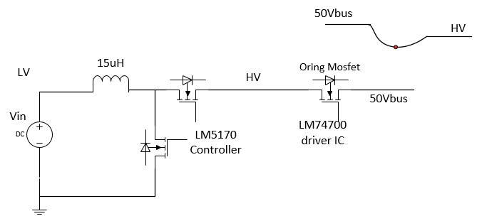
How to ramp up the boost converter of LM5170 speedy?

The circuit is below: While 50Vbus is less than HV, the LM5170 boost deliver the power through oring mosfet.

I am looking for what kind parameter of LM5170 to improve the ramp up.

So far, it doesn't help while SS capacitor 25nF change to 1nF in simulation model.

Because each simulated result takes 3~4 hours. So could you please help to suggest what parameter is key for LM5170.

BTW, the waiting time is from LM5170 , not Oring Fet turn-on delay. (Viewed by simulation result)

Thank,

Aska Lee

Test condition: Vin 44V, Vo 48V, Fsw 250Khz, Inductor 15uH.

  • Hi Aska,

    Thank you for considering the LM5170.  How fast do you want the circuit to catchup? It sounds you monitor the 50V, and when it drops to a certain level your turns on the LM5170, right?  If so, you may turn-on the LM5170 to keep it alive, then you can have faster transition for HV to take over the power delivery. 

    If possible, you can show us your complete schematic then we can review and comment for specific modifications. 

    Thanks,

    Youhao Xi, Applications Engineering

  • Hi Youhao:

    Thanks for your reply.

    Sure, we keep the LM5170 alive.

    By simulated reslut, the voltage drop to 45.19V (from 48Vo) during LM5170 backup the Vbus.

    Finally, the voltage drop is improved to 46.3V by replaced choke Inductance and modified the feedback compensation.

    Is there any way to improve voltage drop? (eg. modify the parameter of LM5170)

    Thanks.

    Aska

    lm5170.pdf

  • Hi Aska,

    Can you share your schematic?  Sorry I just returned . 

    Thanks,

    Youhao

  • Dear Youhao:

    Sorry for reply late.

    The schematic was attached on 3/9.

    I guess I found the answer by modified the compensation.

    But if you have better idea, please let me know.

    Thanks.