This thread has been locked.

If you have a related question, please click the "Ask a related question" button in the top right corner. The newly created question will be automatically linked to this question.

BQ25883: No USB adapter detected when OTG is turned on

Part Number: BQ25883

Dear experts,

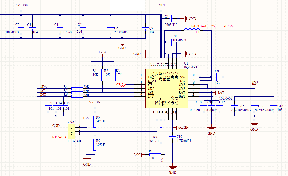
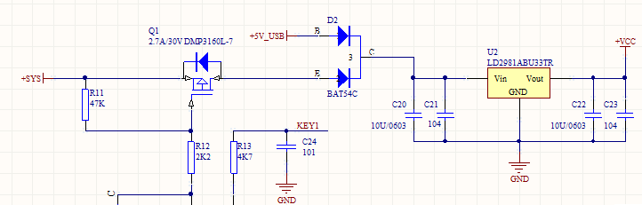
When working in the OTG mode(VBUS_STAT bits are set to 111),  I plug in USB adapter,but I find the i2c resister VBUS_STAT bits are still 111,my schematic is shown as blew,would you please suggest how to change the status resister VBUS_STAT when working in OTG mode.


Thanks.

  • This charger will not automatically turn off OTG when VBUS is being supplied current and then an adapter is plugged in. Once the user knows that the adapter is plugged in, the user needs to disable OTG using the EN_OTG register field.

    Thanks,

    Mike Emanuel

    Please click "This resolved my issue" button if this post answers your question.

  • Dear Michael,

    I should disable OTG using the EN_OTG register field, but the device can't detect adapter plugging in when working in OTG mode .How can the device know  an adapter is plugged in?I can't find any changes when reading VBUS_STAT. Then, in my schematic,D+ and D- are not connected .Does this affect detect an adapter plugging in?

    Thanks.

  • As stated previously, the charger will not be able to detect an adapter when OTG mode is enabled. In order to detect if an adapter is plugged in, OTG mode must be disabled and the adapter must rise above VVBUS_UVLO_RISING. 

    -Mike Emanuel

     "This resolved my issue"

  • 在我的示意图中,我使用OTG模式打开设备的电源,因此OTG始终处于打开状态,但这导致当前无法关闭OTG的情况,否则设备将关闭电源。当设备从没有输入源的电池供电时,无法检测到适配器插入。也许这是我的原理图设计的问题。您能帮我看看我的原理图有何改进吗?然后我可以使用电池为设备供电,而无需始终打开OTG。我的sch  如下图所示。

    谢谢。

  • What are you "powering on?" The part does not require OTG to be on to power it on. If the battery is above VBAT_UVLO_RISING, the part will turn on. Can you please clarify your question?

    Thanks,

    Mike Emanuel

  • Sorry, I sent the wrong message. My question is as follow,

    In my schematic, I use OTG mode to turn on the power on the device, so the OTG is always on, but this causes to the current situation that the OTG cannot be turned off, otherwise the device will turn off the power. Adapter plugging in cannot be detected when device power up from battery without input source. Maybe that's the problem with my schematic design. Can you help me to see how my schematic can be improved?Therefore, I can use the battery to power the device without always turning on the OTG. My schematic is shown above.

    As stated previously, The part does not require OTG to be on to power it on. If the battery is above VBAT_UVLO_RISING, the part will turn on. Therefore, my understanding of device power up from battery without input source is wrong. In order to raise the bat voltage above the UVLO threshold(VBAT_UVLO_RISING) , What should be improved in the schematic diagram?


    Thanks.

  • I think there is still a disconnect here. In the first paragraph of the last response, you say you use OTG mode to power on the device. You do not need to use OTG to turn on the charger. Even if you had a system load, as stated in page 20 of the datasheet, the system will be powered by the battery as long as the battery is above the minimum system voltage. Therefore, no OTG is required to turn on the part nor the system.

    In the second paragraph of the last response, you state the part does not require OTG to turn on. This is correct.

    As said earlier, if you have OTG enabled, you cannot detect the input source. If you want to be able to detect the adapter, you need to disable OTG.

    Thanks,

    Mike Emanuel

    Please click "This resolved my issue" button if this post answers your question.

  • Sorry.Maybe I didn't explain why I used OTG. Our circuit needs to supply power to the motor, and we need to provide a stable 5V power supply, that is, VIN in the schematic diagram, so we always let OTG turn on. If we use sys to supply power to the motor according to section 8.3.2 of the manual, because the battery voltage is greater than 5V, we need to add a step-down chip, and at the same time, we will increase the cost. Thank you for your answer.

  • Our part cannot simultaneously supply power to Vin and take power from it. If you need a 5 V rail, I would recommend connecting it from your 5V adapter through a diode and from the battery connection using an LDO. This way you will have a stable 5 V power supply. Please let me know if you have any other questions.

    Thanks,

    Mike Emanuel

    Please click "This resolved my issue" button if this post answers your question.

  • Could you better explain the load you require (how much power it consumes)? This will help me answer your question better. I actually think you could use a buck converter to convert from the battery voltage to your load, but I need more specifics about your load. How stable does this supply need to be?

    Thanks,

    Mike Emanuel

    Please click "This resolved my issue" button if this post answers your question.

  • The main load is two motors, MCU and several LED. One motor has a starting current of 2a and a running current of 500mA. The other motor has a starting current of about 500mA and a running current of 500mA. In our current design, the voltage of the two motors is provided by Vin. For the power supply of MCU and leds, the SYS of bq25883 is used to provide power through a diode or a 5V adapter through a diode and connected to LDO, so that the adapter and battery can supply power to the equipment. The current consumption of MCU and leds is about 20mA. Now there are two main problems: 1. Detecting the insertion of the adapter when only the battery is powered; 2. If the adapter type is unknown, how to set the charging current to 500mA.


    Thanks.

  • The motors and leds must run stably for about 30 minutes after the equipment is powered on.

    Thanks.

  • I found a solution.The two motors will be shut down for 60ms each cycle and run alternately for other times, about 500ms each cycle.I'm sorry I didn't let you know in advance about this condition. During the period when both motors are turned off, I turn off OTG, and then the device can successfully detect the adapter. At the same time, it will not affect the normal operation of the motor.Thank you for your answer.

    Thanks.

  • Happy to help!

    Please click "This resolved my issue" button if your question was answered.