This thread has been locked.

If you have a related question, please click the "Ask a related question" button in the top right corner. The newly created question will be automatically linked to this question.

TPS23754: PD detection problem.

Part Number: TPS23754
Other Parts Discussed in Thread: PMP

Hello,

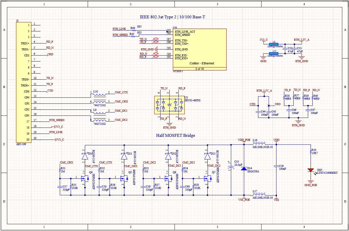
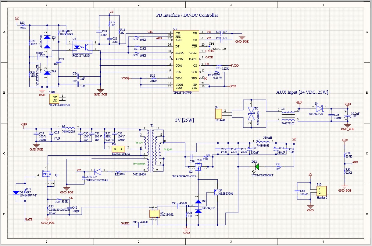
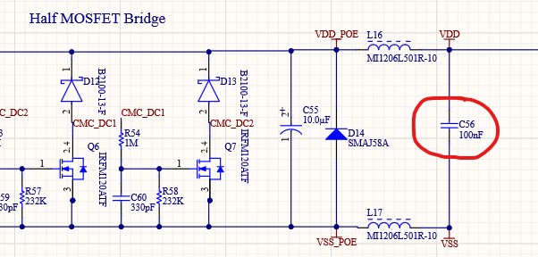
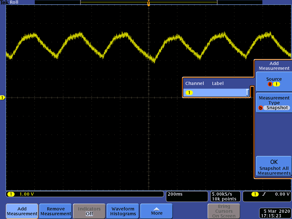
We have a custom design with TPS23754. The schematic is similar to PMP6672B [in SLVA475]. At the moment the VDD-VSS voltage doesn't reach 10V.

Here is the VDD-VSS level:

The current in VDD line is measured with a multimeter and it ranges from 0.1 to 0.14 mA. This seems to indicate a good effective resistance for PD detection.

How to fix this problem?

  • Hello Raghuveer,

    How are you powering the device?

    Can you provide a schematic?

    If this post answers your question, please indicate so by marking this thread as resolved. Thank you.


    Regards, 


    Michael P.

    Applications Engineer

    Texas Instruments 

  • The device is powered by HPE 2530-8G-PoE+ Ethernet Switch

    Here are the schematics:

    At the moment I have removed the MOSFET related components in the rectifier bridge and replaced them with B2100-13-F diodes.

  • Hello,

    Thank you for the information. When you probe VDD-VSS, can you see a valid detection and classification signature before the waveform provided?

    If this post answers your question, please indicate so by marking this thread as resolved. Thank you.


    Regards, 


    Michael P.

    Applications Engineer

    Texas Instruments 

  • There was no valid detection and classification signature. VDD-VSS is like this from the begining.

  • So this narrows it down to something wrong with the way it is getting detected. Reviewing your schematic, it appears there is no 0.1uF capacitor between VDD-VSS which is required to set the AC impedance for a valid detection in IEEE802.3.at standard. Please add this and let me know about the results. 

    If this post answers your question, please indicate so by marking this thread as resolved. Thank you.


    Regards, 


    Michael P.

    Applications Engineer

    Texas Instruments 

  • Isn't this the capacitor you mentioned?

  • Hello,

    Yest that is the capacitor.

    If the detection and classification settings are correct on the PD schematic, then my suggestion is that there could be something either broken or incorrect on the board.

    I would first try powering the board with a DC-DC power supplies to ensure everything is working properly. Then I would check that the components that normally break (IC, FETs, diodes, BJT, etc). are not broken. Then I would check that the values in the schematic are in fact the values on the board. 

    Lastly, you could get the EVM or PMP board to do a side by side test. This will reveal the differences between the boards and hopefully reveal the issue.

    If this post answers your question, please indicate so by marking this thread as resolved. Thank you.


    Regards, 


    Michael P.

    Applications Engineer

    Texas Instruments