This thread has been locked.

If you have a related question, please click the "Ask a related question" button in the top right corner. The newly created question will be automatically linked to this question.

BQ25713: What is the minimum charging current for the BQ25713 charger?

Part Number: BQ25713
Other Parts Discussed in Thread: TPS2121

What is the minimum charging current for the BQ25713 charger??

I am asking this because of a solar panel charger application using microcontroller for MPPT with BQ25713.

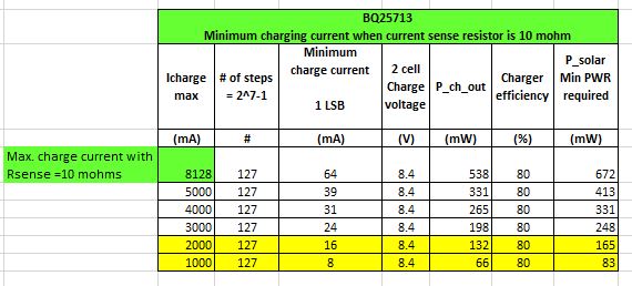
In the datasheet, it is mentioned that charge current can be digitally set in 64mA increments, LSB=64 mA.

Does it mean that input power needs to be sufficient to provide output charging current minimum 64mA?
Or the minimum charging current could be from 0mA to 64mA??

How charger behaves if the minimum charging current needs to be 64mA, but input power is not sufficient to support such output charging current?

Input power could be from a wall adapter or from solar panel.

If the minimum output current needs to be 64mA, in the case of 4 battery cells, output charging power is P_ch_out_min=4 x 4.2V x 64mA=1,075 W.
Minimum solar panel output power, in that case, needs to be:
P_solar_min= P_ch_out_min+P_ch_losses, which is total about 1.2W.

Not to be able to use available solar panel power  bellow 1W, would be quite a big limitation.


I need clarification.
Thanks,

Regards,

Spring2020

=========

  • Hey Spring2020,

    The minimum programmable charging current for this charger is 64mA, same as the LSB. The limitation is the sensing accuracy, which in this scenario would require maybe a 20mOhm sense resistor instead of the typical 10mOhm for higher power applications.

    However, I want to point out that in a solar panel application like this, the programmed charge current usually does not play a role. I tell customers using panels to just set the charge current to the battery maximum current, even if the panel cannot provide this.

    The reason is our charger's VINDPM feature. When you pull current from a panel, the voltage begins to droop further away from the open circuit voltage (VOC). By default, our charger reads the unloaded panel voltage when applied and sets the VINDPM threshold to VBUS - 1.28V. This feature will effectively regulate the input voltage to that value before it can be loaded beyond its capability and cause the voltage to dropout. 

    In VINDPM, the charge current is automatically reduced to regulate the input voltage at VBUS to the InputVoltage() register setting (default is VBUS,unloaded - 1.28V). So even if you program 3A, the charger will not allow it as it attempts to keep VBUS from the panel from collapsing. 

    Regards,

    Joel H

  • Thanks,
    Q1: Is controller reading Solar Panel voltage only the first time when it detects input voltage, or is it doing periodically during charging by disabling charging for a short period of time?
    Q2: Solar panel Voc voltage and optimal working voltage drifts significantly over temperature range -40 +85  for about ( + - 5V).
    Will BQ25713 be able to track these voltage changes efficiently?
    Q3: Let's analyze a scheme when input power can be from any DC power supply or from Solar Panel.
     
    There is one input connector with just one pin for Vin_DC or Solar Panel voltage.
    The customer can plug-in any DC wall adapter from 9 - 24V, or 12V car battery or Solar Panel.
    The voltage and power rating of these DC sources is unknown.
    Is it possible to set the charger to be able to deal with these different input power sources on its own without causing collapse of power sources?
    Or we need some additional circuits and MCU to support the charger controller?
    Thanks and regards,
    Spring2020

    ============

  • Hey Spring2020,

    For Q1: It is only determining this the initial plug in of the solar panel, or whenever the input drops below the UVLO threshold and comes back up (this scenario can occurs will a heavily shaded panel). 

    For Q2: This charger does not track the temperature variation of VOC. You would have to, on your host controller, both monitor the panel temperature and set the RESET_VINDPM bit on ChargeOption3() register in order to reset the InputVoltage() regulation point to the new VOC - 1.28V. 

    For Q3: On their own, whenever an input is applied, the VINDPM threshold is always recalculated to VBUS,unloaded - 1.28V, whether it be USB, 12V car battery, or solar panel. Ideally with USB or the 12V car battery inputs, you would program the IIN_HOST() registers to a value in order to match the specified current limit of that type of port, meaning the charger would hit IINDPM regulating the input current as opposed to VINDPM, which regulated input voltage. 

    You will always need an MCU to use this charger, but that MCU is further needed to truly implement input source management as well as a realistic MPPT algorithm for the solar panel.

    Regards,

    Joel H

  • Hi Joel,

    Thank you for details.

    From  BQ25713 datasheet, Table 4. Charger Command Summary (page 33,), with the assumption that sense resistor is 10 mohms,

    it can be seen that there is 7-bit ChargeCurrent() register, to setup charge current.


    I created a spreadsheet to calculate minimum charge current = 1 LSB, where I varied maximum charge current.

    Looks like the maximum charge current needs to be reduced down to about 1 or 2 amps, in order to be able to use low available power from the solar panel.

    In that case, sense resistor value needs to be increased.

    That would allow using cheaper low power solar panels 2W,  or 5W.

     To have both options, high and low charging current, the current sense circuit gets a little bit more complex.

    That can be achieved by a combination of one sense resistor in parallel with the other resistor plus PFET transistor. Rs1 || (Rs2+PFET)

    PFET would be turned on when high charging current. That is in the case when a wall adapter is connected.

    But, the biggest challenge is how to detect when a  solar panel is connected.

     Here is what I think.

    MCU first disables charger and measures input voltage.

    After that, MCU enables charger by setting initial low charging current.

    Next step is to increase charging current and monitor voltage.

    If wall adapter is connected, presumably it has reasonable low output resistance, so the output voltage is not going to drop that much.

    I am assuming solar panel voltage will drop more rapidly and that would be a sign of solar panel presence on the input.

    Problem with this scheme is if the source voltage is, for example, a cheap, high output resistance wall adapter.

    We don't know what customers may connect as a power source.


    Any comment, and suggestion on this detection scheme,  is very welcome.

    Thank you,

    Regards,

    Spring2020

  • Hey Spring2020, 

    When it comes to charging current, it would be more advantageous to consider the LSB as a differential voltage rather than a current. 

    And instead, the current that flows would be function of the differential voltage / Rsense.

    In this scenario, the LSB is actually 0.64mV (640uV) across all cases. 

    To be quite honest with you, I don't believe your MCU has to do that much work. The charger has integrated loops to account for a solar-type input, namely the VINDPM loop. Under VINDPM, the programmed charging current does not matter because the charger under VINDPM will automatically reduce the charge current anyway.

    The other challenge to solve for you are two different input source types, which I would implement with a power mux, like the TPS2121. With this device, you can program the first channel as the priority being the USB adapter, and the second power source is the solar panel.

    Regards,

    Joel H