Other Parts Discussed in Thread: TM4C123GH6PM
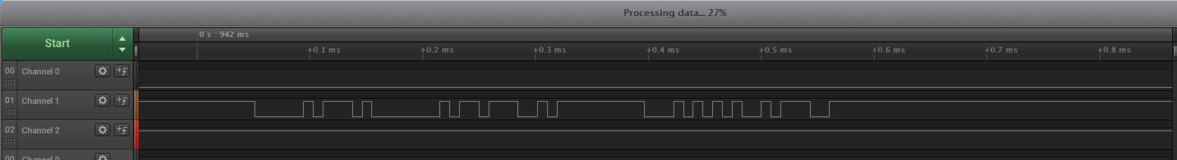
I am in the process of programming the BQ79606A-Q1 using the TI Tiva TM4C123GH6PM with UART communications. After reading extensively through the example code provided for the BQ79606A with the hercules microcontroller I was able to translate that into my own functions that could be used to write to certain addresses of the BQ. After using a logic analyzer I was able to confirm the UART transmission of the Tiva was working properly and sending the correct bit stream along with the correct CRC value. I also created a breakout board for the BQ79606A in order to make proper connections to the Tiva. I connected the 3.3V source of the Tiva to VIO of the BQ79606A as well as using pull up resistors to VIO to connect WAKEUP, NFAULT, TX, and RX to the correct pins. I used a multimeter to double check that all the connections were correct between the Tiva and BQ, which they were. After doing all of this I am still unable to receive any message at all back from the BQ79606A. Since I don't think there is a fault in any of the connections, can someone take a look at my code and see if you can catch any errors when initializing the transmission for the BQ79606A, thank you. I will also provide the screen shot from the logic analyzer which used the command " Broadcastwrite(SYSFLT1_FLT_RST, 0xFF); " to test the UART transmission from the Tiva.
#include <stdint.h>
#include <stdbool.h>
#include <stdio.h>
#include <stdlib.h>
#include <time.h>
#include "inc/tm4c123gh6pm.h"
#include "inc/hw_memmap.h"
#include "inc/hw_types.h"
#include "driverlib/sysctl.h"
#include "driverlib/interrupt.h"
#include "driverlib/gpio.h"
#include "driverlib/timer.h"
#include "driverlib/can.h"
#include "driverlib/uart.h"
#include "driverlib/uart.c"
#include "driverlib/pin_map.h"
#include "driverlib/bq79606.h"
#include "inc/hw_ints.h"
#include "driverlib/interrupt.h"
//**********************
//DELAY FUNCTIONS
//**********************
void delay (unsigned int secs)
{
unsigned int retTime = time(0) + secs; // Get finishing time.
while (time(0) < retTime); // Loop until it arrives.
}
void delayms(uint32_t ui32Ms) {
// 1 clock cycle = 1 / SysCtlClockGet() second
// 1 SysCtlDelay = 3 clock cycle = 3 / SysCtlClockGet() second
// 1 second = SysCtlClockGet() / 3
// 0.001 second = 1 ms = SysCtlClockGet() / 3 / 1000
SysCtlDelay(ui32Ms * (SysCtlClockGet() / 3 / 1000));
}
void delayus(uint32_t ui32Us) {
SysCtlDelay(ui32Us * (SysCtlClockGet() / 3 / 1000000));
}
//**********************
//END DELAY FUNCTIONS
//**********************
//**********************
//CRC Function
//**********************
const uint16_t crc16_table[256] = { 0x0000, 0xC0C1, 0xC181, 0x0140, 0xC301,
0x03C0, 0x0280, 0xC241, 0xC601, 0x06C0, 0x0780, 0xC741, 0x0500, 0xC5C1,
0xC481, 0x0440, 0xCC01, 0x0CC0, 0x0D80, 0xCD41, 0x0F00, 0xCFC1, 0xCE81,
0x0E40, 0x0A00, 0xCAC1, 0xCB81, 0x0B40, 0xC901, 0x09C0, 0x0880, 0xC841,
0xD801, 0x18C0, 0x1980, 0xD941, 0x1B00, 0xDBC1, 0xDA81, 0x1A40, 0x1E00,
0xDEC1, 0xDF81, 0x1F40, 0xDD01, 0x1DC0, 0x1C80, 0xDC41, 0x1400, 0xD4C1,
0xD581, 0x1540, 0xD701, 0x17C0, 0x1680, 0xD641, 0xD201, 0x12C0, 0x1380,
0xD341, 0x1100, 0xD1C1, 0xD081, 0x1040, 0xF001, 0x30C0, 0x3180, 0xF141,
0x3300, 0xF3C1, 0xF281, 0x3240, 0x3600, 0xF6C1, 0xF781, 0x3740, 0xF501,
0x35C0, 0x3480, 0xF441, 0x3C00, 0xFCC1, 0xFD81, 0x3D40, 0xFF01, 0x3FC0,
0x3E80, 0xFE41, 0xFA01, 0x3AC0, 0x3B80, 0xFB41, 0x3900, 0xF9C1, 0xF881,
0x3840, 0x2800, 0xE8C1, 0xE981, 0x2940, 0xEB01, 0x2BC0, 0x2A80, 0xEA41,
0xEE01, 0x2EC0, 0x2F80, 0xEF41, 0x2D00, 0xEDC1, 0xEC81, 0x2C40, 0xE401,
0x24C0, 0x2580, 0xE541, 0x2700, 0xE7C1, 0xE681, 0x2640, 0x2200, 0xE2C1,
0xE381, 0x2340, 0xE101, 0x21C0, 0x2080, 0xE041, 0xA001, 0x60C0, 0x6180,
0xA141, 0x6300, 0xA3C1, 0xA281, 0x6240, 0x6600, 0xA6C1, 0xA781, 0x6740,
0xA501, 0x65C0, 0x6480, 0xA441, 0x6C00, 0xACC1, 0xAD81, 0x6D40, 0xAF01,
0x6FC0, 0x6E80, 0xAE41, 0xAA01, 0x6AC0, 0x6B80, 0xAB41, 0x6900, 0xA9C1,
0xA881, 0x6840, 0x7800, 0xB8C1, 0xB981, 0x7940, 0xBB01, 0x7BC0, 0x7A80,
0xBA41, 0xBE01, 0x7EC0, 0x7F80, 0xBF41, 0x7D00, 0xBDC1, 0xBC81, 0x7C40,
0xB401, 0x74C0, 0x7580, 0xB541, 0x7700, 0xB7C1, 0xB681, 0x7640, 0x7200,
0xB2C1, 0xB381, 0x7340, 0xB101, 0x71C0, 0x7080, 0xB041, 0x5000, 0x90C1,
0x9181, 0x5140, 0x9301, 0x53C0, 0x5280, 0x9241, 0x9601, 0x56C0, 0x5780,
0x9741, 0x5500, 0x95C1, 0x9481, 0x5440, 0x9C01, 0x5CC0, 0x5D80, 0x9D41,
0x5F00, 0x9FC1, 0x9E81, 0x5E40, 0x5A00, 0x9AC1, 0x9B81, 0x5B40, 0x9901,
0x59C0, 0x5880, 0x9841, 0x8801, 0x48C0, 0x4980, 0x8941, 0x4B00, 0x8BC1,
0x8A81, 0x4A40, 0x4E00, 0x8EC1, 0x8F81, 0x4F40, 0x8D01, 0x4DC0, 0x4C80,
0x8C41, 0x4400, 0x84C1, 0x8581, 0x4540, 0x8701, 0x47C0, 0x4680, 0x8641,
0x8201, 0x42C0, 0x4380, 0x8341, 0x4100, 0x81C1, 0x8081, 0x4040 };
uint16_t CRC16(uint8_t *GenCRC, int nLen)
{
uint16_t wCRC = 0xFFFF;
int i;
for (i = 0; i < nLen; i++)
{
wCRC ^= (*GenCRC++) & 0x00FF;
wCRC = crc16_table[wCRC & 0x00FF] ^ (wCRC >> 8);
}
printf("%u\n", wCRC);
return wCRC;
}
//**********************
//End CRC Function
//**********************
//**********************
//BQ79606A READ AND WRITE
//**********************
void BroadcastRead(uint16_t RegAddr, uint8_t Data)
{
uint8_t Init = 0xC0;
//Calculate CRC
uint8_t RegAddr_1;
uint8_t RegAddr_2;
uint16_t CRCresult;
uint8_t CRCresult_1;
uint8_t CRCresult_2;
int size = 4;
RegAddr_1 = (RegAddr & 0xFF);
RegAddr_2 = (RegAddr >> 8);
uint8_t GenCRC[4] =
{
Init, RegAddr_2, RegAddr_1, Data
};
CRCresult = CRC16(GenCRC, size);
UARTCharPut(UART1_BASE, Init); //Transmit the initialization byte
UARTCharPut(UART1_BASE, RegAddr_2); //Transmit the register address
UARTCharPut(UART1_BASE, RegAddr_1); //Transmit the register address
UARTCharPut(UART1_BASE, Data); //Transmit how many bytes of data are being requested
UARTCharPut(UART1_BASE, CRCresult_2); //Transmit CRC
UARTCharPut(UART1_BASE, CRCresult_1); //Transmit CRC
}
void BroadcastWrite(uint16_t RegAddr, uint8_t Data)
{
uint8_t Init = 0xD0;
//Calculate CRC
uint8_t Data_1;
uint8_t RegAddr_1;
uint8_t RegAddr_2;
uint16_t CRCresult;
uint8_t CRCresult_1;
uint8_t CRCresult_2;
int size = 4;
Data_1 = Data;
RegAddr_1 = (RegAddr & 0xFF);
RegAddr_2 = (RegAddr >> 8);
uint8_t GenCRC[4] =
{
Init, RegAddr_2, RegAddr_1, Data_1
};
CRCresult = CRC16(GenCRC, size);
CRCresult_1 = (CRCresult & 0xFF);
CRCresult_2 = (CRCresult >> 8);
UARTCharPut(UART1_BASE, Init); //Transmit the initialization byte
UARTCharPut(UART1_BASE, RegAddr_2); //Transmit the register address
UARTCharPut(UART1_BASE, RegAddr_1); //Transmit the register address
UARTCharPut(UART1_BASE, Data); //Transmit how many bytes of data are being requested
UARTCharPut(UART1_BASE, CRCresult_2); //Transmit CRC
UARTCharPut(UART1_BASE, CRCresult_1); //Transmit CRC
}
void SingleRead(uint8_t DevAddr, uint16_t RegAddr, uint8_t Data)
{
uint8_t Init = 0x80;
//Calculate CRC
uint8_t RegAddr_1;
uint8_t RegAddr_2;
uint16_t CRCresult;
uint8_t CRCresult_1;
uint8_t CRCresult_2;
int size = 5;
RegAddr_1 = (RegAddr & 0xFF);
RegAddr_2 = (RegAddr >> 8);
uint8_t GenCRC_2[5] =
{
Init, DevAddr, RegAddr_2, RegAddr_1, Data
};
CRCresult = CRC16(GenCRC_2, size);
UARTCharPut(UART1_BASE, Init); //Transmit the initialization byte
UARTCharPut(UART1_BASE, DevAddr); //Transmit the device address you are requesting data from
UARTCharPut(UART1_BASE, RegAddr_2); //Transmit the register address
UARTCharPut(UART1_BASE, RegAddr_1); //Transmit the register address
UARTCharPut(UART1_BASE, Data); //Transmit how many bytes of data are being requested
UARTCharPut(UART1_BASE, CRCresult_2); //Transmit CRC
UARTCharPut(UART1_BASE, CRCresult_1); //Transmit CRC
}
void SingleWrite(uint8_t DevAddr, uint16_t RegAddr, uint8_t Data)
{
uint8_t Init = 0x80;
//Calculate CRC
uint8_t Data_1;
uint8_t RegAddr_1;
uint8_t RegAddr_2;
uint16_t CRCresult;
uint8_t CRCresult_1;
uint8_t CRCresult_2;
int size = 5;
Data_1 = Data;
RegAddr_1 = (RegAddr & 0xFF);
RegAddr_2 = (RegAddr >> 8);
uint8_t GenCRC[5] =
{
Init, DevAddr, RegAddr_2, RegAddr_1, Data_1
};
CRCresult = CRC16(GenCRC, size);
UARTCharPut(UART1_BASE, Init); //Transmit the initialization byte
UARTCharPut(UART1_BASE, DevAddr); //Transmit the device address you are requesting data from
UARTCharPut(UART1_BASE, RegAddr_2); //Transmit the register address
UARTCharPut(UART1_BASE, RegAddr_1); //Transmit the register address
UARTCharPut(UART1_BASE, Data); //Transmit how many bytes of data are being requested
UARTCharPut(UART1_BASE, CRCresult_2); //Transmit CRC
UARTCharPut(UART1_BASE, CRCresult_1); //Transmit CRC
}
//**********************
//END BQ79606A READ AND WRITE
//**********************
//**********************
//BQ79606A WAKEUP
//**********************
void WakeUp79606 ()
{
GPIOPinWrite(GPIO_PORTD_BASE, GPIO_PIN_1, 0x00);
delayus(250);
GPIOPinWrite(GPIO_PORTD_BASE, GPIO_PIN_1, GPIO_PIN_1);
}
//**********************
//END BQ79606A WAKEUP
//**********************
//**********************
//AUTO ADDRESS SEQUENCE
//**********************
void AutoAddress()
{
//memset(response_frame2,0,sizeof(response_frame2)); //clear out the response frame buffer
uint8_t nCurrentBoard;
//dummy write to ECC_TEST (sync DLL)
BroadcastWrite(ECC_TEST, 0x00);
//clear CONFIG in case it is set
BroadcastWrite(CONFIG, 0x00);
//enter auto addressing mode
BroadcastWrite(CONTROL1, 0x01);
//set addresses for all boards in daisy-chain
for (nCurrentBoard = 0; nCurrentBoard < TOTALBOARDS; nCurrentBoard++)
{
BroadcastWrite(DEVADD_USR, nCurrentBoard);
}
//set all devices as a stack device
BroadcastWrite(CONFIG, 0x02);
//if there's only one board, its the base and top of stack
if(TOTALBOARDS == 1)
{
SingleWrite(0, CONFIG, 0x01);
}
else
{
//set the base and top of stack individually
SingleWrite(0, CONFIG, 0x00); //base
SingleWrite(TOTALBOARDS-1, CONFIG, 0x03); //top of stack
}
}
//**************************
//END AUTO ADDRESS SEQUENCE
//**************************
//**************************
//Voltage Conversion Formula
//**************************
float Complement(uint16_t rawData, float multiplier)
{
return -1*(~rawData+1)*multiplier;
}
//**************************
//End Voltage Conversion Formula
//**************************
//Begin Main Function
int main(void)
{
//Enable Peripheral Clocks
SysCtlClockSet(SYSCTL_SYSDIV_4 | SYSCTL_USE_PLL | SYSCTL_OSC_MAIN | SYSCTL_XTAL_16MHZ);
SysCtlPeripheralEnable(SYSCTL_PERIPH_GPIOA);
SysCtlPeripheralEnable(SYSCTL_PERIPH_GPIOB);
SysCtlPeripheralEnable(SYSCTL_PERIPH_GPIOC);
SysCtlPeripheralEnable(SYSCTL_PERIPH_GPIOD);
SysCtlPeripheralEnable(SYSCTL_PERIPH_GPIOF);
SysCtlPeripheralEnable(SYSCTL_PERIPH_UART1);
//Configure the GPIO Pin Mux for PF2 to Charge Button
GPIOPinTypeGPIOInput(GPIO_PORTF_BASE, GPIO_PIN_2);
GPIOPadConfigSet(GPIO_PORTF_BASE, GPIO_PIN_2, GPIO_STRENGTH_2MA, GPIO_PIN_TYPE_STD_WPD);
//Configure the GPIO Pin Mux for PF3 to Arduino Fault
GPIOPinTypeGPIOInput(GPIO_PORTF_BASE, GPIO_PIN_3);
GPIOPadConfigSet(GPIO_PORTF_BASE, GPIO_PIN_3, GPIO_STRENGTH_2MA, GPIO_PIN_TYPE_STD_WPD);
//Configure the GPIO Pin Mux for PC4 to Arduino Brake Input
GPIOPinTypeGPIOInput(GPIO_PORTC_BASE, GPIO_PIN_4);
GPIOPadConfigSet(GPIO_PORTC_BASE, GPIO_PIN_4, GPIO_STRENGTH_2MA, GPIO_PIN_TYPE_STD_WPD);
//Configure the GPIO Pin Mux for PB3 to Tractive System Light
GPIOPinTypeGPIOOutput(GPIO_PORTB_BASE, GPIO_PIN_3);
GPIOPinWrite(GPIO_PORTB_BASE, GPIO_PIN_3, 0x0);
//Configure the GPIO Pin Mux for PC5 to Ready To Drive Sound
GPIOPinTypeGPIOOutput(GPIO_PORTC_BASE, GPIO_PIN_5);
GPIOPinWrite(GPIO_PORTC_BASE, GPIO_PIN_5, 0x0);
//Configure the GPIO Pin Mux for PB4 for CAN0RX
GPIOPinConfigure(GPIO_PB4_CAN0RX);
GPIOPinTypeCAN(GPIO_PORTB_BASE, GPIO_PIN_4);
//Configure the GPIO Pin Mux for PB5 for CAN0TX
GPIOPinConfigure(GPIO_PB5_CAN0TX);
GPIOPinTypeCAN(GPIO_PORTB_BASE, GPIO_PIN_5);
//Configure the GPIO Pin Mux for PD0 to NFAULT
GPIOPinTypeGPIOInput(GPIO_PORTD_BASE, GPIO_PIN_0);
GPIOPadConfigSet(GPIO_PORTD_BASE, GPIO_PIN_0, GPIO_STRENGTH_2MA, GPIO_PIN_TYPE_STD_WPU);
//Configure the GPIO Pin Mux for PA5 to Ignition Switch
GPIOPinTypeGPIOInput(GPIO_PORTA_BASE, GPIO_PIN_5);
GPIOPadConfigSet(GPIO_PORTA_BASE, GPIO_PIN_5, GPIO_STRENGTH_2MA, GPIO_PIN_TYPE_STD_WPD);
//Configure the GPIO Pin Mux for PA6 to Reset Switch
GPIOPinTypeGPIOInput(GPIO_PORTA_BASE, GPIO_PIN_6);
GPIOPadConfigSet(GPIO_PORTA_BASE, GPIO_PIN_6, GPIO_STRENGTH_2MA, GPIO_PIN_TYPE_STD_WPD);
//Configure the GPIO Pin Mux for PA2 to Precharge AIR
GPIOPinTypeGPIOOutput(GPIO_PORTA_BASE, GPIO_PIN_2);
GPIOPinWrite(GPIO_PORTA_BASE, GPIO_PIN_2, 0x0);
//Configure the GPIO Pin Mux for PA4 to Positive Terminal AIR
GPIOPinTypeGPIOOutput(GPIO_PORTA_BASE, GPIO_PIN_4);
GPIOPinWrite(GPIO_PORTA_BASE, GPIO_PIN_4, 0x0);
//Configure the GPIO Pin Mux for PA3 to Negative Terminal AIR
GPIOPinTypeGPIOOutput(GPIO_PORTA_BASE, GPIO_PIN_3);
GPIOPinWrite(GPIO_PORTA_BASE, GPIO_PIN_3, 0x0);
//Configure the GPIO Pin Mux for PD1 to WAKEUP
GPIOPinTypeGPIOOutput(GPIO_PORTD_BASE, GPIO_PIN_1);
GPIOPinWrite(GPIO_PORTD_BASE, GPIO_PIN_1, GPIO_PIN_1);
//Configure the GPIO Pin Mux for PB0 to U1RX
GPIOPinConfigure(GPIO_PB0_U1RX);
GPIOPinTypeUART(GPIO_PORTB_BASE, GPIO_PIN_0);
//Configure the GPIO Pin Mux for PB1 to U1TX
GPIOPinConfigure(GPIO_PB1_U1TX);
GPIOPinTypeUART(GPIO_PORTB_BASE, GPIO_PIN_1);
UARTConfigSetExpClk(UART1_BASE, SysCtlClockGet(), 1000000, (UART_CONFIG_WLEN_8 | UART_CONFIG_STOP_ONE | UART_CONFIG_PAR_NONE));
UARTEnable(UART1_BASE);
IntMasterEnable(); //enable processor interrupts
IntEnable(INT_UART1); //enable the UART interrupt
UARTIntEnable(UART1_BASE, UART_INT_RX | UART_INT_RT); //only enable RX and TX interrupts
//Configure red led
GPIOPinTypeGPIOOutput(GPIO_PORTF_BASE, GPIO_PIN_1);
//Configure green led
GPIOPinTypeGPIOOutput(GPIO_PORTF_BASE, GPIO_PIN_2);
//Configure blue led
GPIOPinTypeGPIOOutput(GPIO_PORTF_BASE, GPIO_PIN_3);
//BQ79606A Initialization
WakeUp79606();
delayms(7*TOTALBOARDS); //Transition time from shutdown to active - 7ms from wake receive to wake propagate for each device
AutoAddress(); //Address each IC in the BMS
BroadcastWrite(SYSFLT1_FLT_RST, 0xFF); //reset system faults
BroadcastWrite(SYSFLT2_FLT_RST, 0xFF); //reset system faults
BroadcastWrite(SYSFLT3_FLT_RST, 0xFF); //reset system faults
BroadcastWrite(SYSFLT1_FLT_MSK, 0xFF); //mask system faults (so we can test boards and not worry about triggering these faults accidentally)
BroadcastWrite(SYSFLT2_FLT_MSK, 0xFF); //mask system faults (so we can test boards and not worry about triggering these faults accidentally)
BroadcastWrite(SYSFLT3_FLT_MSK, 0xFF); //mask system faults (so we can test boards and not worry about triggering these faults accidentally)
BroadcastWrite(COMM_CTRL, 0x3E); //Set baud rate to 1Mbps
BroadcastWrite(DAISY_CHAIN_CTRL, 0x3F); //enable daisy chain comm
//Set up main ADC
BroadcastWrite(CELL_ADC_CTRL, 0x1F); //enable conversions for cells 1-5
BroadcastWrite(CELL_ADC_CONF2, 0x08); //set continuous ADC conversions, and set minimum conversion interval
BroadcastWrite(CONTROL2, 0x01); //CELL_ADC_GO = 1
delayus(3*TOTALBOARDS+ 901); //3us of re-clocking delay per board + 901us waiting for first ADC conversion to complete
while (1)
{
//IC Test
int i = 0;
int32_t response;
SingleRead(0, VCELL1H, 0x01); //Request 2 bytes of data for cell 1
//bool Avail = UARTCharsAvail(UART1_BASE);
//printf("%d\n", Avail);
response = UARTCharGet(UART1_BASE);
printf("%d\n", response);
}
}