This thread has been locked.

If you have a related question, please click the "Ask a related question" button in the top right corner. The newly created question will be automatically linked to this question.

LM61460: Is the 0-dB crossover frequency(100KHz) qualified?

Part Number: LM61460

Hello Guys,

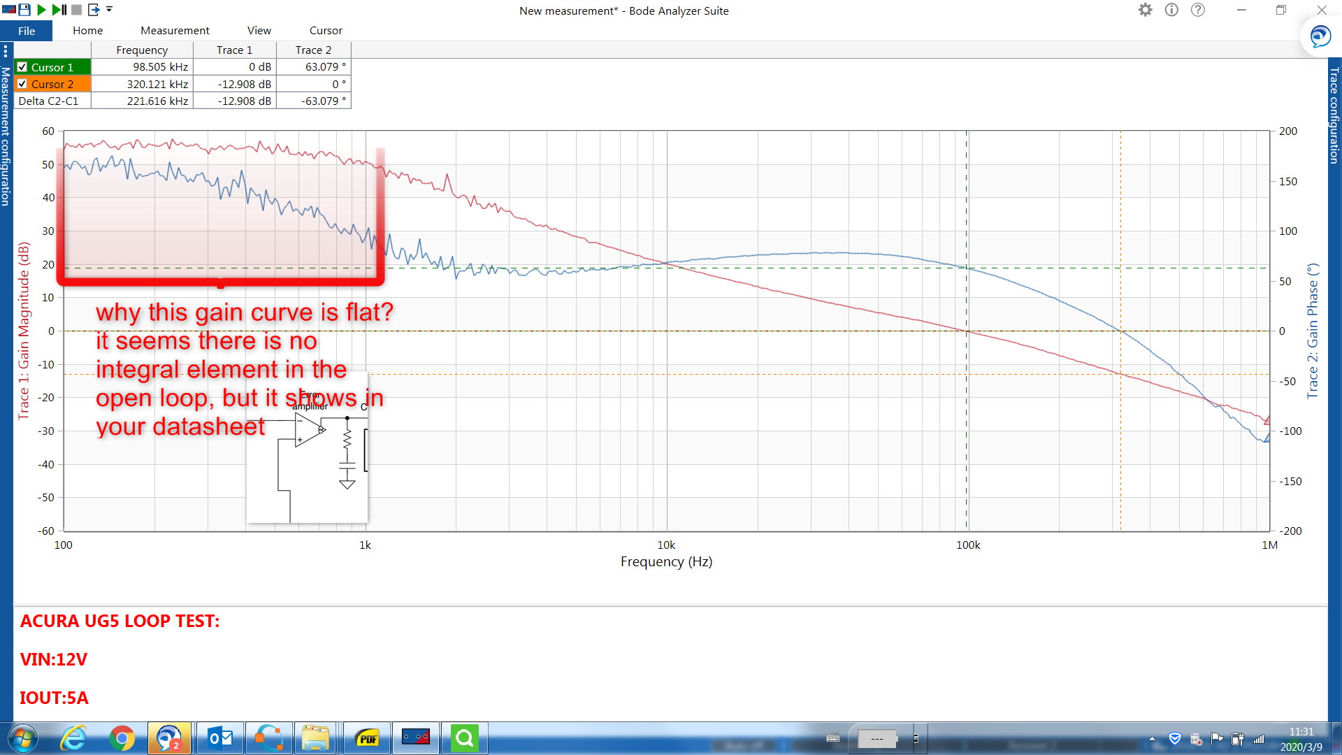
I have performed the loop test on LM61460(5V out,2MHz) buck solution, the curves are below:

I have two questions for you ,hope you can help.

<1>why the highlighted region’s gain curve is flat and the phase is happened to 180 degree at low frequency? I think no integral element effects at those region, but your datasheet show you have one integral element in the loop. Can you explain that? Or can you show your transfer function of your converter’s compensation stage?

<2> the 0-db crossover frequency is about 100KHz(switching frequency is 2.1MHz,from this perspective, it makes sense),can you confirm that this value is qualified to suppress the parameter variations in feedback elements? Another expression is do you think the high frequency noise in the feedback stage can be effectively decreased squeezed under this condition? 

Thanks very much!

  • Hi Jason,

    As for your questions:

    1) the first pole is due to a pole caused by Rload and Cout. This is a normal characteristic of current mode control type of device

    http://www.ti.com/lit/an/slvae26a/slvae26a.pdf

    2) I believe that the loop crossover frequency seems reasonable at 100kHz. As far as noise concern i think it depends on the layout for the device and the gain is well attenuated at 2.1MHz if there is a noise due to FB noise

    Thanks

    -Arief

  • Hello Arief,

    Thanks for your quick response.

    <1> there is a pole at origin in the loop compensation stage, that means the Gain Curve will decrease  approximately linearly at the very beginning of the frequency in semilogx descartes  coordinate system ,but the gain curve is flat, and also if the open loop just has only one origin pole, the Phase is about 90 degree at the beginning of the frequency, but the phase measured is 180 degree. those are my confusions.

    <2> i am agreed with your opinion, my concerning is that there are two concepts: sensitivity function S and complementary sensitivity function T, and between them, there is a so-called waterbed effect, generally S + T =1, since S+T=1 always holds, therefore, if you try to push the S further down at low frequencies in order to make the system robust against low frequency disturbances, then the price to pay is that, S will pop up in higher frequencies which makes the system perform very pool at those frequencies. the crossover frequency can influence the S and T. this is a trade-off.

    yet if you can confirm that the crossover frequency set to be 100KHz is OK, i will follow you criteria .


    Thanks

    Best Regards,

    Jason

  • yet if you can confirm that the crossover frequency set to be 100KHz is OK, i will follow you criteria .

    100kHz crossover is good.

    Close to 1/10 of switching frequency is ideal.