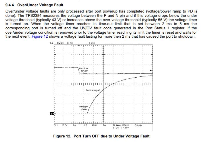
Part Number: TPS2384EVM
Hello team,
Hope you are doing well, Would you mind helping with below customer question:
We have a product here which uses a LM5073. The LM5073 is now obsolete and the recommended substitute is a TPS2376. I modified one of our product that used the LM5073 to use the TPS2376 instead.
To test the modification I made on our product, I’m using a TPS2384 Evaluation Module as my PoE injector. I want to test how the TPS2376 reacts when the PoE voltage levels are either 37V or 57V. I was under the impression that using the TPS2384 eval module, I was allowed to apply anywhere between 37V and 57V as its power supply, and in automatic (AM) mode, it would deliver this voltage on the Ethernet lines (after detection and classification). Somehow, I can put in a voltage of 40V and my PD gets powered on, but if I increase it to 55V, I get cut-off. It is the eval card that is cutting me off.
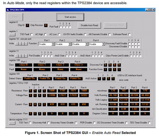
Looking at the TPS2384 datasheet, I don’t understand why I get cut-off. Using an I2C controller, I can look at various register and even write to some of them. One I should be able to control is the Common Control Register (reproduced below, from the datasheet). Bit D2 in specific should allow me to disable the port over/under voltage faults. I have not been successful at writing a 1 in that bit to allow the 57V I want to inject on the Ethernet lines. In fact, when the eval board voltage is raised to 56V, I can read the Port Status Read register as 0x41 (which indicates a UV/OV fault). If it might help, The Common Read Register is 0x06 (meaning I have a TPS2384 rev 1).