This thread has been locked.

If you have a related question, please click the "Ask a related question" button in the top right corner. The newly created question will be automatically linked to this question.

TPS40211-Q1: Contact to a german FAE

Part Number: TPS40211-Q1
Other Parts Discussed in Thread: TPS40211

We need support with our layout design using the TPS40211-Q1 in our led emblem project. Is ist possible to receive a contact of a german FAE?

Or what is the best way to get support from TI?

Thanks a lot.

Best regards

Dennis

  • Hi Dennis,

    Thank you for using the TPS40211-Q1 in your design.  

    If you are comfortable with it, you can send me a private message with your design files and I can review the layout and get back to you with feedback.

    Thanks,

    Richard

  • Hi Richard,

    I have discussed it with my colleague. At first he wants to specify that our schematic is right.
    Can I send you our schematic?

    The most important question is if our idea for the PWM will work.

    Best regards

    Dennis

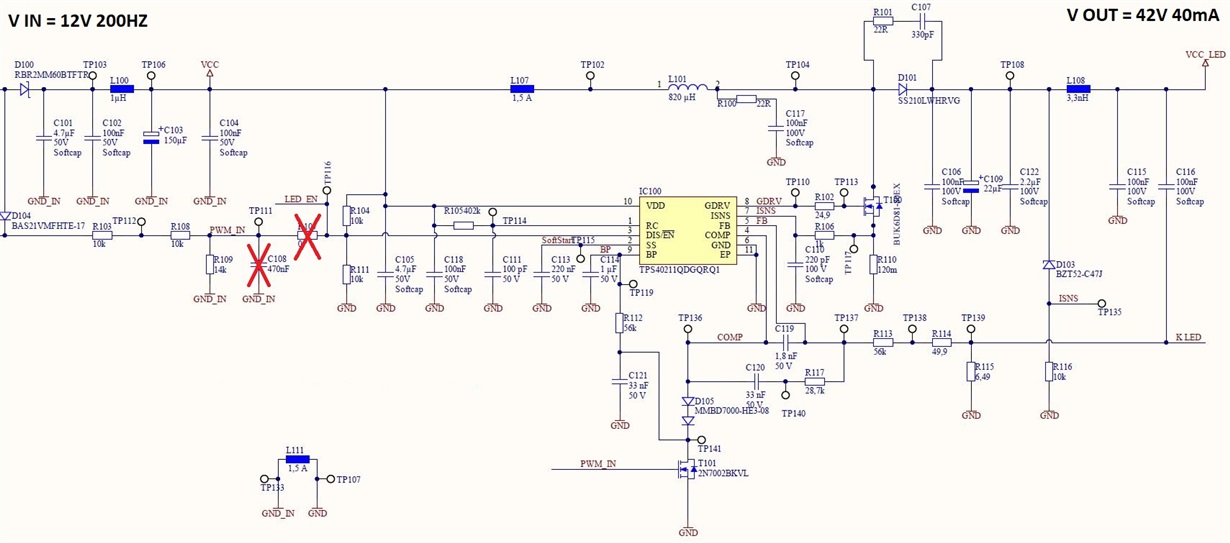
  • Hi again,

    here is the schematic:

    Thank you very much.

    Best regards

    Dennis

  • Hi Dennis, 

    Thanks for sending the schematic. I just have a preliminary question.

    1) Is your input a 12V, 200Hz sinusoidal waveform?

    Your power stage of the converter looks okay, but I will need to examine what you are doing with the DIS/EN and COMP pin more carefully. I can give you my feedback by next week.

    Thanks,

    Richard

  • Hi Richards,

    thanks for your first assessment.

    1) At the moment it is a square wave, but it is not finalized by our customer.

    2) I forgot to cross out the pull down resistor R111. In this case it is not fitted. So our first impression is that we can handle the PWM signal by shutting the IC down via the DIS/EN pin. In our old schemtaic (using an Alegro IC A8513KLYTR)  we do so and it works good. This IC has an internal FET an we have temperature problems, so we decided to use an IC with an external FET --> we think TI is a good choice.
    In simple words: we want to shut down the IC via the PWM signal at the EN Pin to varify the brightness of the LEDs by playing with the duty cycle of the PWM signal. There will be a brightness ramp up at starting time and a brightness ramp down at ending time.
    We orianted us at the datasheet page 33 of the TPS40211 for using PWM signals. We have both attempts to evaluate which on is the best way.

    So, I hope u understand what we try to do and that one of this solutions will work.

    Thanks a lot

    Best regards

    Dennis

  • Hi Dennis,

    Thank you for the comment.

    I think you can modify your design to follow the one listed here: https://www.ti.com/tool/PMP10291

    I think this design provides a better starting point than the one in the datasheet for the following reasons:

    1) The zener diode is connected to the FB instead of the current sense pin. In this case, zener diodes have some leakage, and in your schematic, the zener leakage can flow into the current sense capacitor (C110), providing a DC bias offset. Secondly, connecting the zener to FB will have less leakage, since current will more than likely flow into your 6Ohm resistor instead of the rest of the network. 

    2)  Your connection of BP to T101 is okay so you can reverse bias D105, so this is ok. However, note that when you pull the drain of T101 down, you may draw some more current from the regulator, which may cause power dissipation through R112. 

    Thanks,

    Richard