This thread has been locked.

If you have a related question, please click the "Ask a related question" button in the top right corner. The newly created question will be automatically linked to this question.

BQ76940: DSG_EN signal commutating by itself.

Part Number: BQ76940
Other Parts Discussed in Thread: BQSTUDIO, BQ78350, BQ76200,

Hi there,

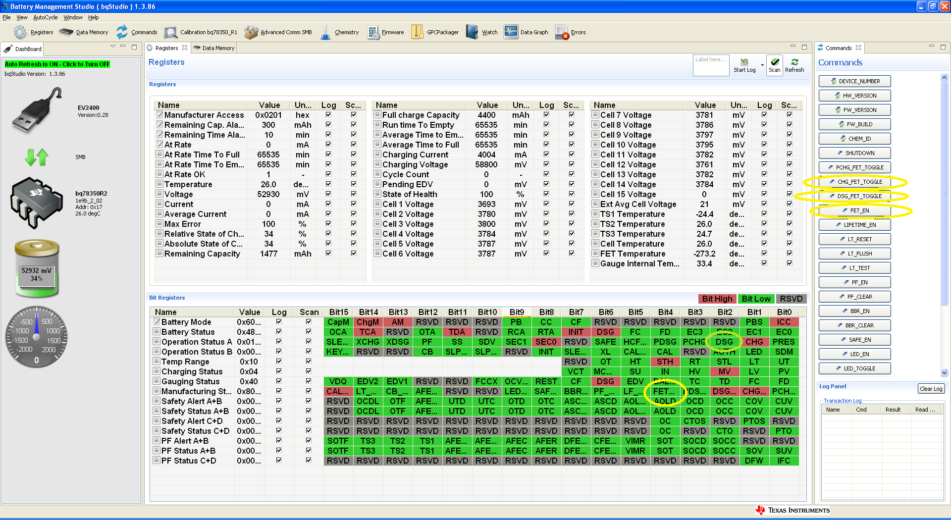
I have been working with the BQ76940EVM. I have updated the R2 firmware and the evaluation board works fine. Via bqStudio, when the “FET_EN” is activated, the CHG and DSG transistor are ON fixed. When the “FET EN” is released the transistor are OFF and can be controlled via the “CHG_FET_TOGGLE” and “DSG_FET_TOGGLE”. Works fine. Nevertheless,


I’m developing my own BMS based on this EVM:

-          BQ7694000 14S1P. The same device.

-          BQ78350 firmware R2. The same device and firmware.

-          BQ76200 with charge and discharge path independent. This is the main difference respect the EVM.


The problem is this:

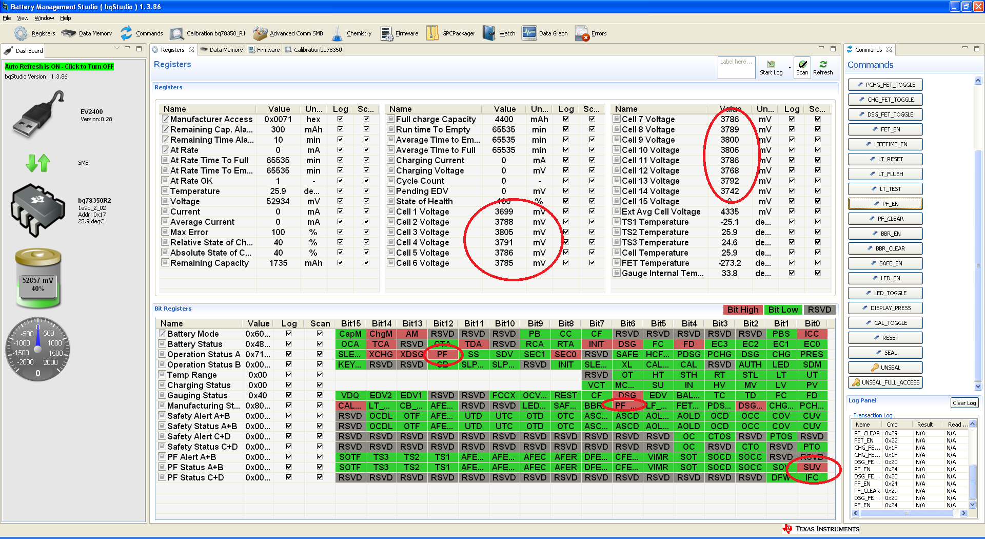
When I activate the “FET_EN” then the DSG and CHG signals are OFF all the time. WHY?

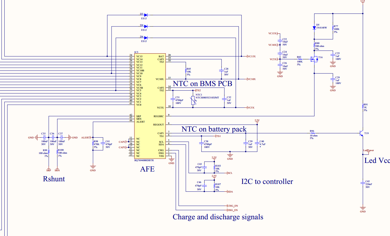
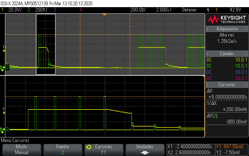
When I deactivated the “FET_EN” and trigger “CHG_FET_TOGGLE” and “DSG_FET_TOGGLE”, the CHG transistor is fixed ON (it’s ok) BUT the DSG transistor is activated BUT just a moment, in fact is activated and deactivated by itself in a loop. Please have a look to the picture. Is the DSG_EN signal from BQ7694000 to the BQ76200. The signal is ON/OFF every second more or less.

Why?

Seems something wrong with DSG_EN signal, the BQ7694000 makes commute in a loop. Why?

Attach some schematic as well.

thanks a lot

  • Hi Albert,

    I think the behavior you are seeing is due to the Body Diode protection feature of the BQ78350. The BQ78350 software is designed to work with a series FET configuration, so it toggles the FETs as needed to prevent them from burning up. This is explained in section 3.1 of the BQ78350-R1 TRM

    Unfortunately, there is no way to disable this feature.

    Regards,

    Matt

  • Hi Matt,

    Thanks a lot for your time.

    I don't think that the body diode protection is the cause. The body diode protection take sense when there is current and now is not my case because there is no current. In fact I have short circuited the Rshunt (so the voltatge is 0) with the same results.

    Some data:

    hardware setup.jpg -> you can see the BMS and the batteries. Note that there is no power supply to charge; and there is no load discharge. So current=0A. The power contacts are on the bottom and they are not visible.

    Discharge voltage and alert signals.png --> You can see the voltatge on DSG path which is 50V but, as I told you, appear and disappear, I mean from 50 to 0. This is because the DSG signal from AFE is activated and deactivated by it self.  In addition you can see the alert signal from the AFE; note that is activated and synchronized when the 50V fall to 0V.

    BQStudio status.png--> Stattus reported by BQstudio.

    In my opinion, the AFE detects something wrong and activated the alert signal. Then the DSG FET is OFF and the voltage fall down. After some seconds recover and loop again.

    You agree?

    So, the question is WHY?

    There is no error flag reported by BQStudio.  ...¿?¿?

    thanks

  • Hi Albert, 

    I see what you mean. It seems like there is a fault present that is causing the DSG FET to turn off. The BQ78350 is likely clearing the fault at the point where you see the activity and then the AFE is again detecting the fault condition. 

    There are a few different fault condition on the AFE that can cause the DSG FET to turn off: UV, OCD, SCD, ALERT override, and AFE_XREADY. Some of these faults should also disable the CHG FET however. Table 1 in the BQ76940 datasheet shows the AFE responses to different fault conditions.

    To debug, I recommend the following steps:

    1. Enable all protections and permanent fail condition on the BQ78350. There are some protections (for example ASCD) that cannot be disabled, but if they are not 'enabled' on the BQ78350, they will not be reported. These include ASCD, AOLD, SOV, SUV, AFE_XRDY, AFE_OVRD.
    2. Using BQStudio, create a log file by clicking 'Start Log' on the Registers screen. This will show what is occurring in the status registers over a period of time and you should be able to see which fault or PF is triggering.
    3. If this does not solve the problem, please save a copy of your data flash settings (.gg file) by clicking the Export button from the Data Memory screen.

    Best regards,

    Matt

  • Hi Matt,

    You are right. I have to enable the PF via "PF_EN" button; and in this case the SUV flag is on. Safety under voltage.

    Note that I have available 14 cells, so the 15th is disable (short on VC15 to VC14 pins). I assume that there is no problem. I have updated the cell map, of course.

    BUT, have a look to the BQ studio print screen, the cell voltages are ok; so where the SUV comes from?

    On the other hand, the calibration, have a look the screen shoot, what I have to introduce on the Vaux paramater?

    Add a oscilloscope picture, where you can see the output voltage from 50 to 0 and the Vaux, which goes to 0,8V to 0

    thanks a lot

  • Hi Matt,

    sorry the picture attached.

  • Hi Albert, 

    I believe the top cell must be connected for the BQ76940. There are tables in the BQ769x0 datasheet showing the cell connections for different cell counts. I think fixing this might resolve the SUV issue.

    Best regards,

    Matt

  • Hi Matt,

    I don't think so.

    I disabled the 15th cell in your EVM and woks fine.

    Do you have more ideas?

    thanks

  • Hi Albert,

    The top cell should be used or it can cause the SUV problem you are seeing. At first, it will operate normally with the top cell measuring 0V. However, as the system starts running, there will be transients as the thermistors are sampled every 2 seconds, so there will be a voltage measurement high enough to make the device think a cell is connected - eventually this can trigger an SUV. It is hard to see this by just observing the BQStudio main screen, but you might be able to see this if you collect log files with a fast enough sample frequency - you may be able to see the Cell 15 voltage jump up every 2 seconds.

    If you modify the cell connections per the datasheet recommendation, this issue should be resolved.

    Best regards,

    Matt

  • Understood.

    Thanks a lot.

    I will check. But I don't now when. .... Now is not easy.

    Thanks a lot.