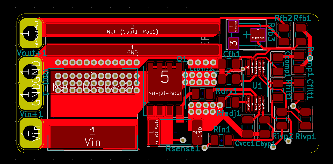
I am using the LM3481 to boost from 3-4.2Vin to 5Vout up to 10A load. My current schematic and board view attached: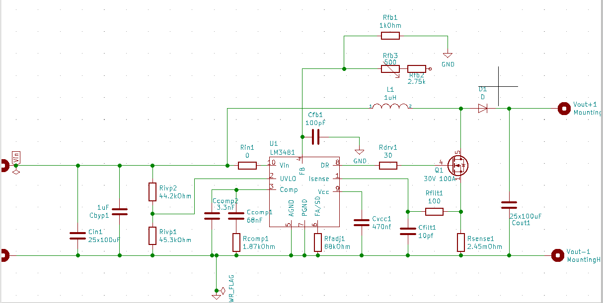
In my previous version of this design, I had no gate resistor, so I was getting bad ringing at the mosfet driver gate as shown: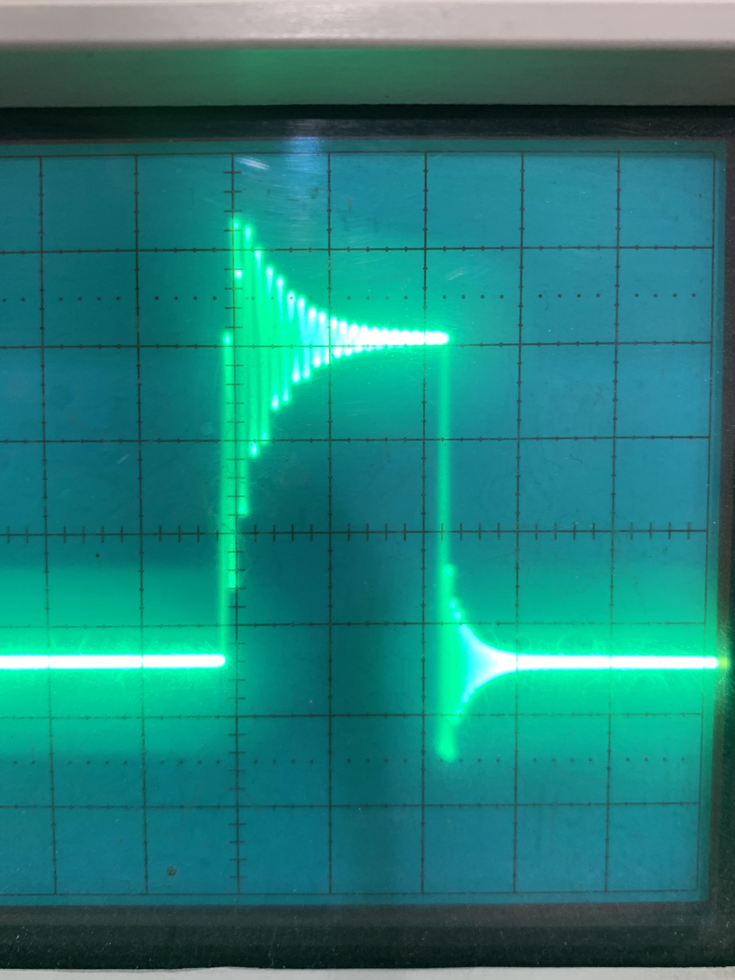
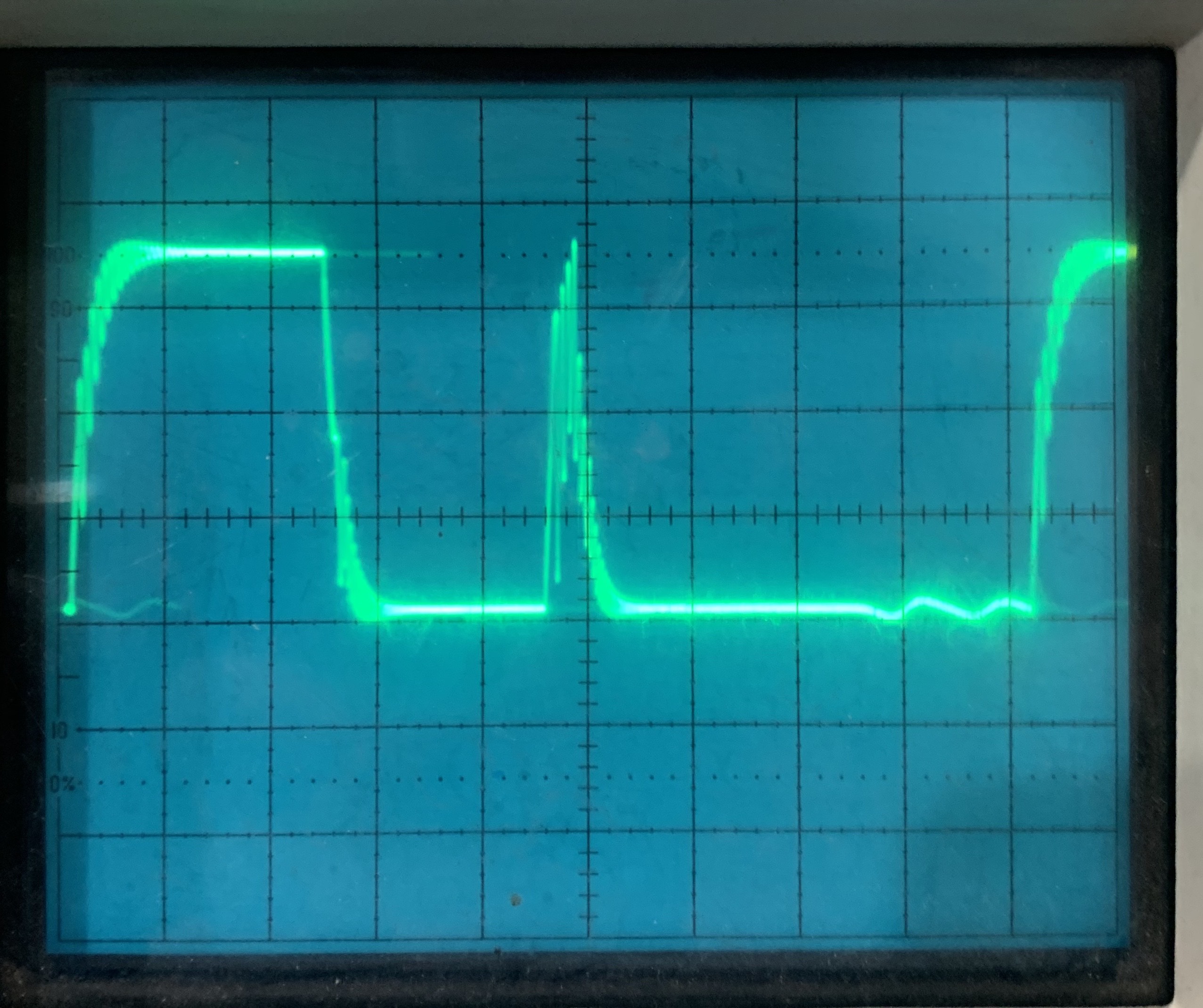
So in this version I added the gate resistor, a small capacitor at the feedback pin (which I'm not yet using) and an option for a resistor at the Vin pin of the controller to make an RC filter (which I have not yet used). I also moved around some components a little to reduce trace lengths. I was hoping these things would help smooth my signal, but it is arguably worse now and I can't figure out why. Here is an image of the waveform at the mosfet gate from my current design with a 30 ohm gate resistor (yes a touch overkill but it's okay for now). My frequency resistor is 88k which sets it to around 250khz.

This is at 1V/div and 1us/div. My Vin is 3.1V for this image, since it gave me the cleanest waveform, and my load was 10W. I also had to play with the trigger a lot because I was getting lots of fuzzy and overlapping waves. From what you can see, there is no longer dramatic ringing, but I cannot explain for the life of me why it is spiking like that.
I replaced the controller thinking it could be a bad part, but no luck.
I measured all my capacitance and resistances and they all check out.
I have 2.5mF of input and output capacitance from low ESR ceramic capacitor arrays.
It is not caused by UVLO, since mine is set to the minimum on voltage - 2.97.
The feedback resistors are set to output 5V.
The IC is humming at various pitches depending on the input voltage.
The output voltage is being boosted to 5V, around 20W it starts to fail. At those higher levels I cannot get any sort of intelligible waveform whatsoever. Is there any insight as to what might be wrong?
As a P.S. this may or may not be insightful to the issue, but at around 3.7Vin and higher, the humming stops, and the waveform cleans up nice and crisp, but it looks even more wrong...
same settings 1V/div, 1us/div.