This thread has been locked.

If you have a related question, please click the "Ask a related question" button in the top right corner. The newly created question will be automatically linked to this question.

TL431: PNP transistor in high current shunt regulator application

Part Number: TL431

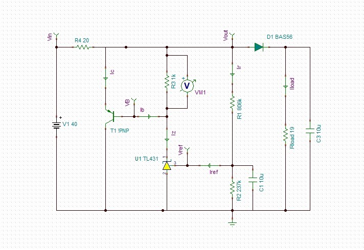
I am using TL431 in the application as High Current Shunt Regulator as mentioned in Datasheet. 

Vin range (14V to 40V) , Vout = 12V , Load ( 40 to 600 mA). 

i would like to understand how does (T1) pnp transistor works in this application .

How do we calculate Ic, R3 and Vout. ?

What is the biasing condition of T1 while Vout is regulated?


12V_Shunt.TSC

  • Hi Nikita,

    In this application the TL431 helps with regulating Vout with T1.

    As you noted there is 3 key factors when designing this type of circuit.

    First is Vout.

    Vout: Vref * (1 + R1/R2) + (Iref * R1)

    The feedback loop that regulates the output now includes T1.

    Second: R4 should be sized on the maximum current you need at the max load + ika(min) + margin

    R4 = [Vin(min) - Vout] / [ILoad(max) + Ika(min) + margin]

    Vin(min) = the minimum Vin where you want the output to regulate.

    Third: R3

    Because during a no load condition, all the current will be divided between Ika + Ic.

    R3 should be sized based on the maximum Ika you want to pass through the TL431.

    VBE( at Vin(max) & ILoad(min)) / ( IKA(max) + Ib) < R3 < VBE(at Vin(min) & ILoad(max)) / Ika(min)

    The current will always be the current that is not through the load + Ika. So choose a T1 that can handle the worst case current

    Ic = (Vin - Vout) / R4 - Ika - ILoad.

    Ic(max) = (Vin(max) - Vout) / R4 - Ika

  • Thank you for quick support. 

    I could calculate and simulate the shunt as per my application. 

    However, while moving across input voltage and load range, i have some observations. 

    I shall consolidate and revert in a few days