Hi,
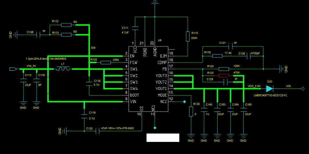
my customer designed the schematic below to convert 5V input to 5.9V output. 9f for ceramic and 9g for resistor means not soldered.
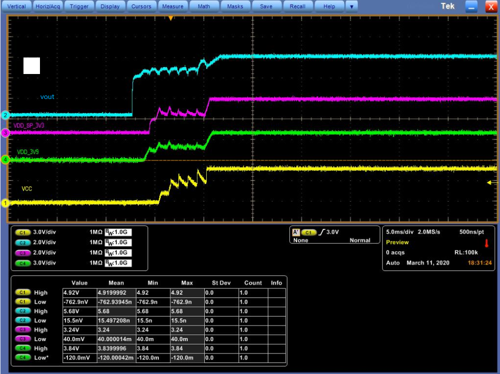
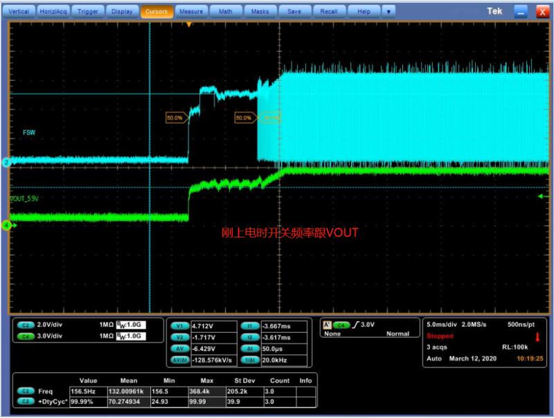
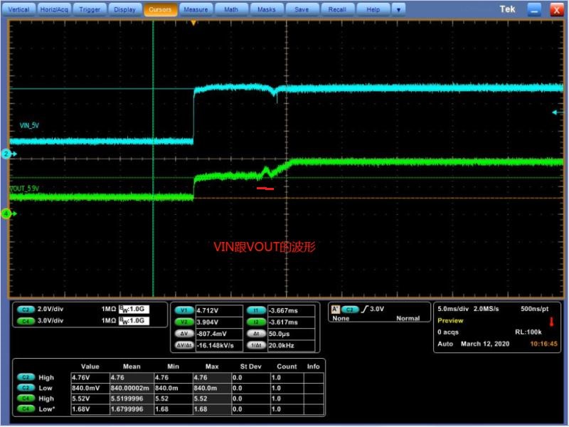
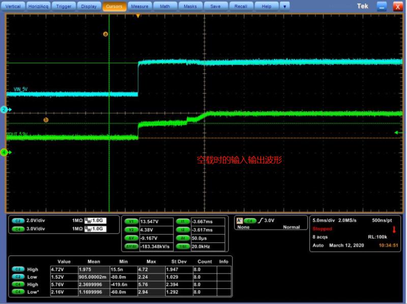
But they find that the output will have large ripple during startup. Blue line below.
The other 3 signals are generated from the 5.9V output so they can be ignored.
Why are there ripple during startup?