This thread has been locked.

If you have a related question, please click the "Ask a related question" button in the top right corner. The newly created question will be automatically linked to this question.

CCS/BQ24650: Can the BQ24650 chip independently charge multiple batteries in series?

Part Number: BQ24650

Tool/software: Code Composer Studio

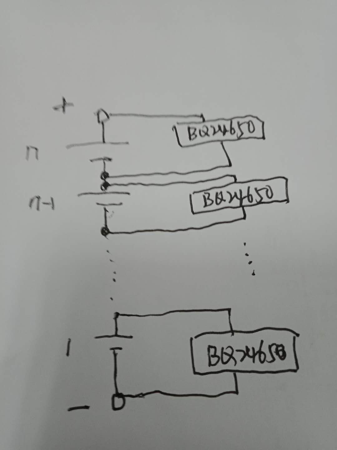
Single lithium battery, charging cut-off voltage = 2.6v, charging current =2A, multiple connections in series.A single BQ24650 chip sets output voltage = 2.6v and charging current =2A. A single BQ24650 is charged separately for series batteries. Is this circuit ok?If there is any question, please specify, thank you!

  • In a general sense yes. However, each bq24650 requires an isolated supply (for example using a flyback converter) in order to stack the batteries. May I ask if you are charging a supercapacitor? Also, what is your end equipment?

    Thanks,

    Mike Emanuel

    Please click "This resolved my issue" button if this post answers your question.

  • Each BQ24650 input power supply is equipped with 1 DC/DC module, the input and output of this module are isolated. The input of each DC/DC module is a DC stabilized power supply. After the module isolates the output, it provides power to BQ24650, and the output of BQ24650 is charged by multiple lithium batteries in series, as shown in the figure above.BQ24650 input power DC24V by diode PDS1040 buck, access to BQ24650 1 pin VCC= 23.5v, then the circuit MPPT voltage is set to 23V, is it ok?R11 = 1 m Ω, R7 = 56 k Ω, see below.

    Now the charging line is relatively long (about 1 meter), resulting in the battery voltage = 2.4v, and the measured voltage at the SRN and SRP terminals is 2.55v. The problem is that the charging current is only about 1A, which cannot reach my requirement of 2A.Adjust the charging voltage to about 3.2v, and the current can reach 2A. Could you please tell me how to solve this problem?

    Thank you for your reply

  • Can you please provide a full schematic? I am unsure if you are using multiple BQ24650s to charge multiple cells, or one BQ24650 to charge all the cells. I also need to see how the rest of the pins are connected to give a full and accurate answer.

    In addition, I am unsure of your MPPSET resistor values. Please ensure they follow page 14 of the datasheet. If R11 = 1 MOhm and R7 = 56 kOhm then your V_MPPSET should be about 22.628 V.

    V_MPPSET = 1.2*(1+R3/R4)

    If the voltage on the MPPSET pin drops, the charge current is reduced to maintain input voltage. If the MPPSET is forced below 1.2 V, the output current is reduced to zero while the bq24650 stays in the input voltage regulation loop. In addition, if MPPSET is reduced below 75 mV, charge is disabled.

    The problem of the charge current lies in the length of the cable. The chip will regulate the battery voltage at the pin, not the battery. The battery may not be fully charged, but at the SRN pin you may read regulation voltage. I would recommend shortening your connection to the battery if you are able.

    Thanks,

    Mike Emanuel

    Please click "This resolved my issue" button if this post answers your question.

  • The battery pack is composed of 60 single batteries in series. A single BQ24650 charges a single battery, and a total of 60 BQ24650 are used.Each 24650 input power supply is provided by isolated DC/DC module 24V, and 24V power supply is isolated separately.

    The single charge circuit diagram is shown below。

  • As a disclaimer, this part has not been used in this fashion therefore the support may take longer.

    Can you please report the voltage measured on VFB in each case? Can you capture the transition from 1 A to 2 A?

    Thanks,

    Mike Emanuel

    Please click "This resolved my issue" button if this post answers your question.

  • When the output voltage is set to 2.7v, when the battery is 2.4v, VFB= 2.119v, and the output current = 1.67a;When the output voltage is set to 2.6v, when the battery is 2.4v, VFB= 2.133v, and the output current = 1.23a;

  • I have several ideas, but I am worried that the output voltage is being changed in the middle of a charge cycle. In addition, your impedance to the battery looks like it is on the order of several 100 mohms. If you drop 1 A or more across this, this could cause issues with recharge later.

    However, first can you try the following? Set the output voltage to be fixed at a desired battery voltage. Discharge the battery voltage so that when it is connected to the charger VFB will drop below VLOWV or 1.55 V (without the input connected). Then connect the input. Monitor the charging current throughout the entire cycle. I am concerned that both of the currents in the previous post were accurate, albeit they were measured in the termination phase where the current of the battery is dropped while maintaining constant voltage in order to combat the battery relaxation. If you could provide detailed logs of the voltage at SRN and the actual battery terminal, that would be helpful. Please do not change the battery regulation during a charging cycle.

    Thanks,

    Mike Emanuel

    Please click "This resolved my issue" button if this post answers your question.