This thread has been locked.

If you have a related question, please click the "Ask a related question" button in the top right corner. The newly created question will be automatically linked to this question.

UCC28742: UCC28742 SIMPLIS analysis issue with example model

Part Number: UCC28742

Hi Experts,

I am using UCC28742 simplis model that is shown in ti.com/UCC28742 product page. But I meet two issues:

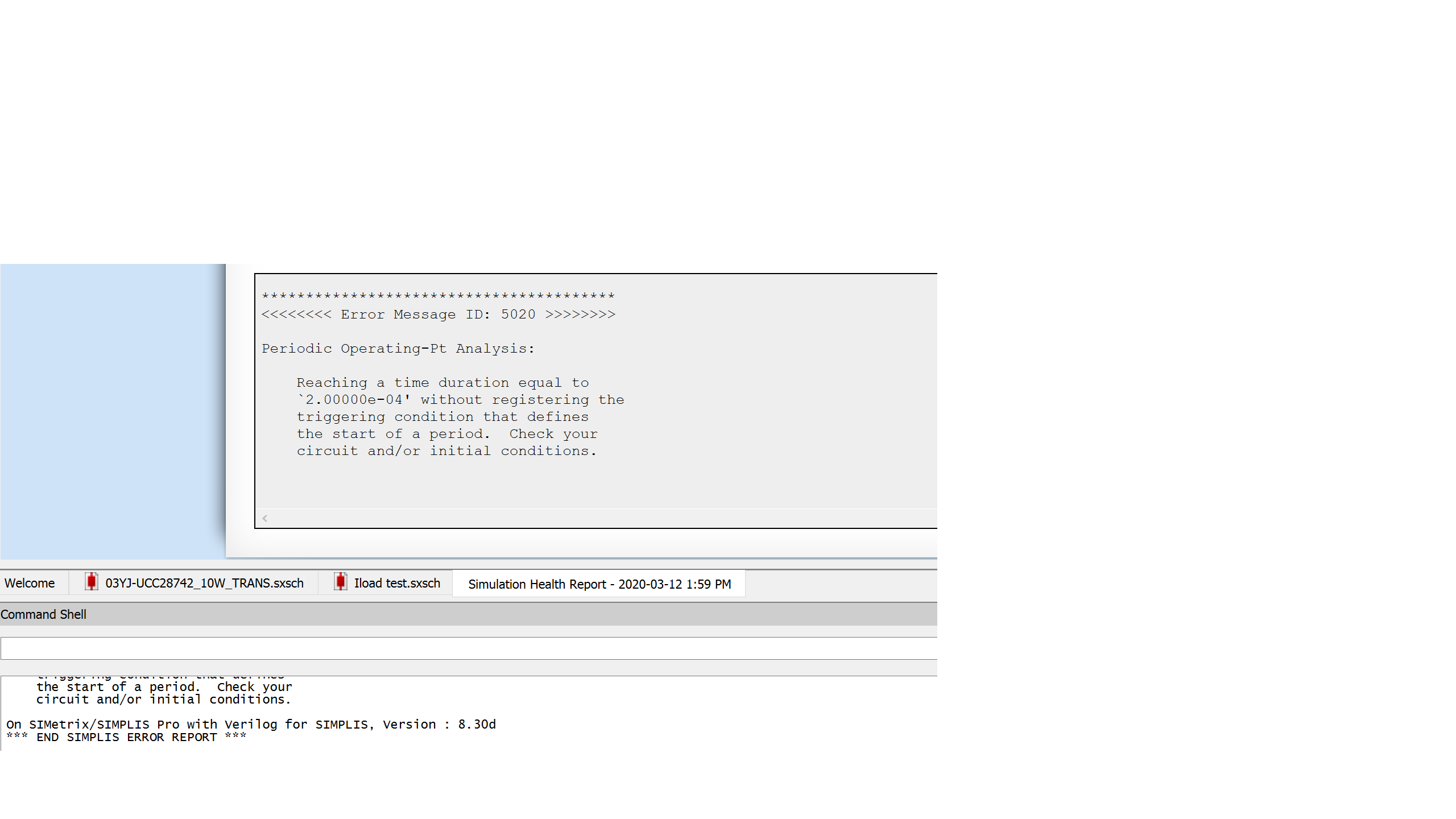
1. I cannot run POP or AC analysis with your example, the error report is shown in below picture, and you can reoccur this issue with the example model. How can I fix it?

2. This example is designed for 85V~265V input, right? But I cannot start up the converter at 85V input.  You can reoccur the waveform of 85V input, the circuit I use is TI example circuit. How can I fix it?

Thank you.

Rachel

  • Hello Rachel,


    Thank you for your interest in the UCC28742 flyback controller.


    I ran the simulation and got the same result as you did. I tried different POP settings but still got similar errors.  Since this controller operates with valley-switching and frequency dithering (for EMI reduction), I believe that there simply is no periodic operating point that can be found.  The cycle-by-cycle switching variations are too much for the POP, no matter how insignificant they appear visually. 

    The help file from Simplis states that the POP analysis looks for convergence of repeating states to within very tight accuracy.  Even though this part obviously works well for regulation, I think this device simply does not repeat the cycles with enough consistency to satisfy the POP analysis.

    I don’t think there is any way to fix it.


    For your second question, please be aware that the “85V~265V input” refers to AC volts and are RMS values. The simulation schematic is simplified to eliminate the AC rectification and uses a DC source to run faster.

    The peak of 85Vrms = 120Vdc and if you set the source to 120V, the simulation will run.
    (265Vrms = 375Vdc peak.)


    This simulation does not model the low-frequency ripple voltage on the bulk capacitor (C4) however.
    At full load, this is usually around 70V~80V (instantaneous), but the device will not start at that low voltage.
    At start-up, there is no ripple on Vbulk, so the UCC28742 will start at a higher peak level, then will run at lower bulk voltages that result from AC ripple on the bulk, depending on the size of the bulk cap.


    To run a sim at lower voltages, use a time-variable DC source to start at 120Vdc for ~5ms to get the output up, then drop the source to 70V for the rest of your simulation time.  Or, after 5ms delay, add in a triangle wave source with -50V pk-pk amplitude, 100Hz repetition, in series with the 120Vdc source.  Then you can adjust the dc level and the ripple amplitude  and frequency independently.


    Regards,
    Ulrich