This thread has been locked.

If you have a related question, please click the "Ask a related question" button in the top right corner. The newly created question will be automatically linked to this question.

TPS3700: Desired RT Calculation

Part Number: TPS3700

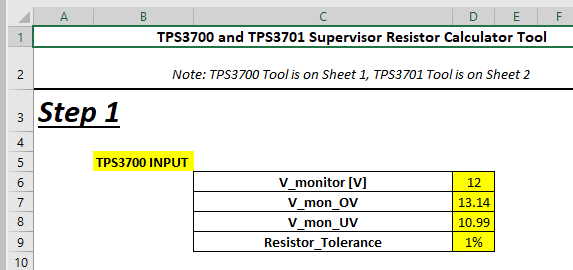
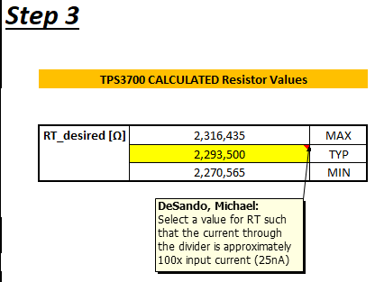
The data sheet says "Select a value for RT such that the current through the divider is approximately 100 times higher than the input current at the INA+ and INB– terminals."  My question is at what voltage?  The example in Section 8.2 in the data sheet and in the Excel calculator are apparently using 5.73V.  Or if it is 12V, then it is using 209.288 times the 25nA input current.  These are not intuitive values, implying that I am missing something.  This could easily be a calculated field in the Excel sheet based on the VMON entry.  The fact that it is not also implies something more is going on.  I would appreciate some clarification.

  • Hi Justin,

    The calculations are based on Vin, desired voltage threshold, and sense current. We have an app note (Optimizing Resistor Dividers at a Comparator Input) that explains this further. Let me know if there is confusion after seeing this.

    Thanks,
    Abhinav.

  • Hello Abhinav,

    Thanks for the reply.  I have already seen that application note and it is completely different from the design procedure that is in the data sheet, so that does not answer my question.  I am trying to understand the example presented in the data sheet on Page 16, Figure 20 and Section 8.2.2.  Also please refer to the Excel spreadsheet that implements the calculations in the data sheet (not the application note) that is here (www.ti.com/.../sluc425). 

    Step 1, enter your values.  Ok, no problem.

    Step 2 is a calculation and Step 3 is where we have the issue.  Both the data sheet and the Excel file say "Select a value for RT such that the current through the divider is approximately 100 times higher than the input current" and the Excel sheet further qualifies this by saying 25nA. 

    But to calculate a resistance you need a current and a voltage, and no voltage is given.  If I select Vuv (10.99) and 100 times 25nA we get 4,396,000 ohms, which is almost double the value in the example.  Work backwards and the 2,293,500 ohms is 100 times the 25nA at 5.73V, which is not a voltage listed anywhere in the documentation.  The example in Figure 18 results in 6.65V, so there is no consistency there.  If we add the input currents for INA+ and INB- and get 40nA, then we get to 9.17V, which is still not a value that lines up with anything else.  All of these values seem to be arbitrary.  If it were truly based on Vin, and voltage thresholds then why is it not calculated based on the information in Step 1?  I must be missing something.

    I don't have time to continue spinning my wheels, so I ask the question, how is that RT derived?  How did Mr. DeSando arrive at 2,293,500?  I would like to understand how the example was done so that I can apply the correct techniques to my design.

    If the value is arbitrary, fine, then say it in the data sheet.  Otherwise, there is missing or incorrect information in the data sheet.  If the method in the application note is the best way, then section 8.2.2 in the data sheet and the Excel file should be revised or removed.  If I am blind and missing something that is in the data sheet, then I would like to know that, too.

  • Hi Justin,

    Let me get Mike DeSando to consult on this for you.

    Thanks,
    Abhinav.

  • Hi Abhinav,

    That would be greatly appreciated.  Thank you.

    Justin

  • Hi Justin,

    Sorry for any confusion. Let me try to clarify some things:

    RT is the total resistance = R1 + R2 + R3

    To measure the approximate current through RT (the entire resistor divider network) during nominal operation, you take the nominal voltage rail being monitored and divide by the total resistance. Or you can take the expected INA+/INB- current x 100 and then solve for the approximate RT. This is to maintain accuracy such that the current through the resistor network doesn't significantly impact the voltage at the INA+/INB- pins. In general, the RT value should be in the megaohms range. This is to not sync too much current to make the solution power consuming, but to sync enough current to provide enough current for INA+ and INB- to not affect the voltage divider measurement.

    To answer your question, RT is derived by a general rule of thumb to set the current through RT much larger than the current required for the INA+/INB- pins for accuracy. For sanity check, take your monitored rail voltage and divide by RT and make sure this is at least 100x larger than 25nA + 15 nA. (25nA comes from the MAX I_INA+ current in table 6.5 and 15nA comes from I_INB-.) If the current through the resistor divider is not high enough, then the current going into INA+, INB- will alter the measured voltage thus affecting the accuracy.

    I hope this is clear. Let me know if there is still any confusion. I want to reiterate that the RT value, that is the three resistors added together, is not a hard requirement but something to keep in mind with the trade off being system Iq vs monitor accuracy. If you are still not sure, set the RT value between 1Mohm and 2Megohm to start.