This thread has been locked.

If you have a related question, please click the "Ask a related question" button in the top right corner. The newly created question will be automatically linked to this question.

LM2776: Unreliable startup, occasionally produces incorrect output

Part Number: LM2776
Other Parts Discussed in Thread: TPS60400

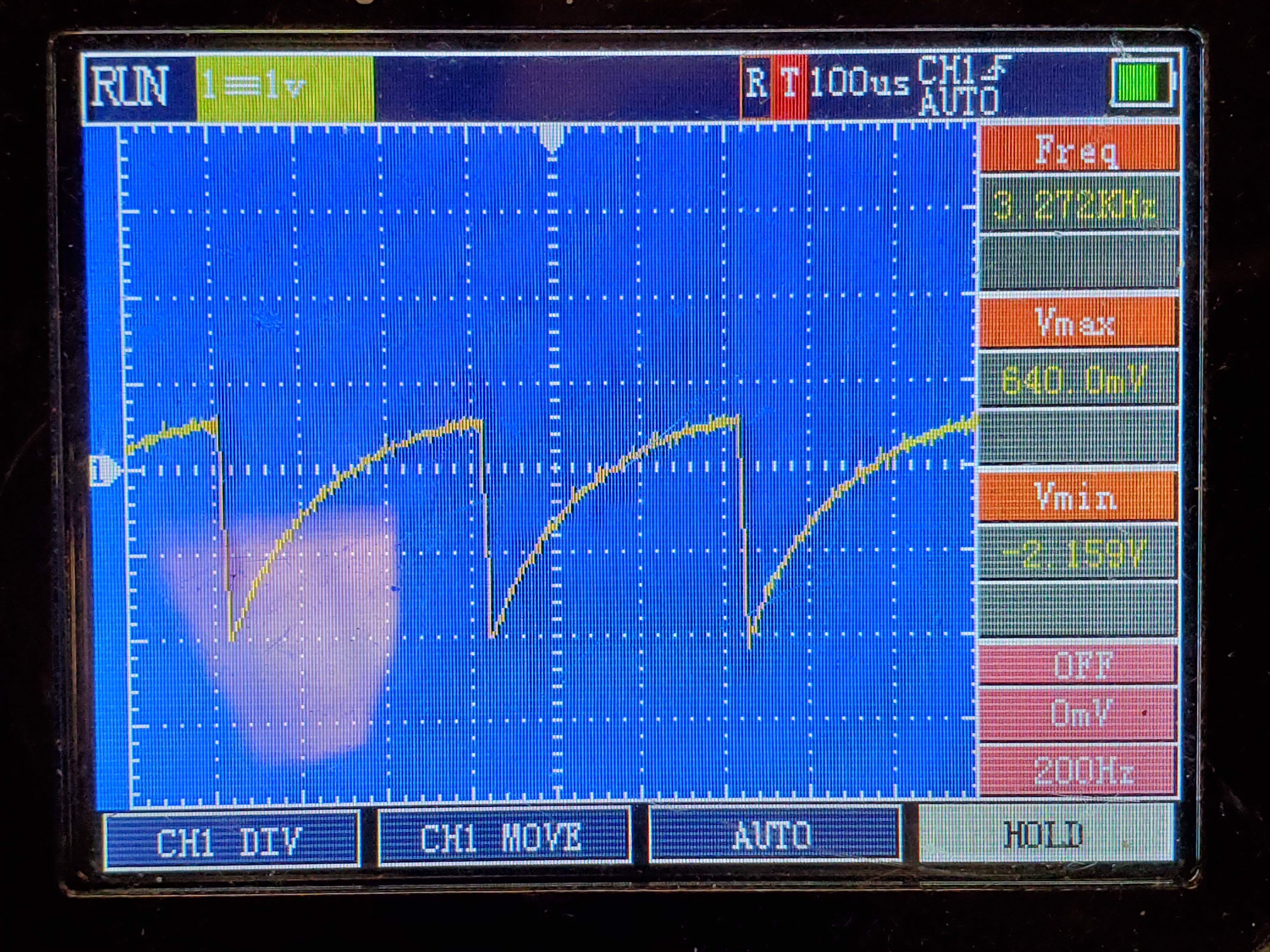
Ive configured the charge pump as per the typical application on page 11 of the datasheet, but for some reason I haven't figured out yet there's a high chance upon power up the output voltage is a very consistent wave from 0.6V down to -2.2V (image from scope below) But this is not always the case. If i simply unplug power from the device and plug it back in whenever the output is resonating the charge pump will eventually give me the -5V i'm expecting, occasionally when i connect power and the voltage is oscillating it may rectify itself after a second or two, but if it doesn't correct itself after a couple seconds it wont ever get to -5V

Things I've checked:

  • Input voltage: Rock steady at 4.9V, no dips or spikes when powered up
  • Various power supplies: Charge pump behaved the same on each supply
  • Add/Removed load from the -5V output: there's a 68ohm resistor soldered to the -5v output, that was not removed for any tests, i've added other resistors to the output but they had minimal impact
  • Adding capacitor to the -5V output: I added a 10uF cap to the output to see if it would help with the resonating, the waveform maintained the same frequency but the max & min peaks shifted to 0V and -2.1V
  • Adding capacitor to the 5V input: no effect

I'm at a loss for what is causing this behavior.


  • Hi Jake,

    Could you please explain your problem again? I am afraid i don't understand completely. Please rephrase only the issue.

    Thanks,

    Febin

  • Febin,

    I'm supplying the device with 4.9V, and expecting it to output roughly -4.9V, instead when i power it up the device usually gives me a ~sawtooth output bouncing between 0.6 and -2.2V.  power cycling the device will eventually get it to output -4.9 but i need it to output th e-4.9 every time.

  • Hi Jake,

    Thank you for the details. 

    I would like to know whether you checked the load current of LM2776 when ever you changed the resistive load. Please only change the resistive load and not the capacitors and provide a load current waveform if possible. The total load (system load+resistive load) should not exceed 200mA. Please ensure this.

    Meanwhile, I will also try to replicate the same measurement setup and check from my side. Please give me some time and will come back to you early next week.

    Regards,

    Febin

  • Using a 4ohm resistor in series with the 5V power supply i pulled this curve during power connection, the peak equates to 675mA of inrush current, most of that is likely due to the 42uF of capacitors on the board. resting current draw with only the 68ohm resistor loading the charge pump is roughly 75mA. This graph was taken from a successful startup of the charge pump.

    Here's the interesting part: the pump fails to work whenever powered by the 5v supply on my usb powered arduino due, but it works perfectly once a 4ohm resistor is in series with its 5v supply. If I start the pump with a normal 5v wire coming from an arduino mega powered by usb it works almost always, if i start the pump with a normal 5v wire coming from an arduino due it fails almost always, if i then connect a 4ohm resistor between 5v and the charge pump the pump continues to provide incorrect output, as soon as i then remove the 5v wire from the pump(thus leaving just the 4ohm resistor supplying the pump) the output immediately corrects, i can then connect the normal 5v to the pump and remove the resistor and the output continues to stay at -4.9v.

    due to that strange behavior i'm unable to get a powerup current curve for when it fails to start.

    It seems the inrush current is too high for the device to startup. the datasheet doesn't specify a over current shutdown, only that the device will limit current draw and likely thermal cycle when >400mA is drawn from the input. I'm doubting that it's internals are thermal cycling at 3.2khz leading to the incorrect output. while 675>400 i would expect it to take longer than 50 microseconds for the device to overheat and shutdown from this current draw.

  • Hi Jake,

    Thank you for sharing the details.

    Due to the current Corona virus issues, we work from home and have no access to conduct measurements. Hence, I request you to do some tests yourself and provide the results and we can discuss further.

    1. Please remove the 68 ohm resistor and use resistive load to vary load current. Please ensure you have a reliable input supply.

    2. Please use the EVM BOM and try to take the measurements again.

    3. I would suggest to first test using a low constant load and then increase the load gradually. The total system load should not exceed the max load current of the device at all times.

    4. For each case, provide the scope plots for Vin, Vout, Voltage across Cfly and load current (important) captured simultaneously.

    (Please remember to make only one change at a time. For eg. keep the BOM same and change the load, change the capacitors as per the datasheet specifications for a particular load, etc.) 

    Please let me know if something is unclear or if you require more explanation.

    Regards,

    Febin

  • Hey Febin,

    unfortunately my scope is only a single input and only capable of measuring voltage, so i wont be able to take simultaneous measurements.

    What exactly are we looking for? i can likely get the information we need if we can narrow the measurement down to one voltage in different test cases.

    As for changing the capacitors, I only see one set of capacitors that are recommended and that's the set i'm currently using, unless there's some table somewhere in the datasheet i cannot find?

    Thanks, Jake

  • Hi Jake,

    I am also not sure what causes your problem, so we need to check one by one. Since I can't do the tests, I requested you to do. I think the device is on your application board. Is my understanding correct?

    (Please make the prob connections for Vin, Vout, Iout and Cfly before itself so that the test setup will not be altered even if you change the probe input to the oscilloscope.)

    -Please follow 1 and 2 above and apply low load for 5V Vin. If you can isolate the rest of the board it will be better. Please provide the four plots with EVM BOM. 

    -Now increase the load for the same BOM and capture the four plots again.  

    Please share the results and we can discuss further.

    Regards, 

    Febin

  • Febin,

    Here's some captures of the Vin, Vout, and Vcfly with the output loaded with 25,50,100,10000 ohms; 10kohms is standing in for no load so i didnt have to keep resoldering the pot. I'm not convinced i'll get representitive data from the Cfly if i put a 4ohm resistor in series with it to measure the current so i didnt take those readings.

    I didnt see anything out of the ordinary here, perhaps you'll see clues as to why this is malfunctioning

    8004.images.zip

  • Hi Jake,

    Please confirm you used the EVM BOM for these measurements.

    Regards,

    Febin

  • Hi,

    Additionally, 25,50,100,100k ohms are total load correct? Do you have an additional system load to the output of the Buck (as shown in the schematic). Is this isolated or not?

    Regards,

    Febin

  • Hey,

    Those resistors were the total load on the LM2776. This device is sharing a 5v and 0v rail with the rest of the circuit board, aside from that it is isolated. Looking at the Vin graph there's no interference from the other devices.

    I'm assuming EVM BOM means recommended components, in which case yes. the circuit is the one i sent in the original message at the top of the thread.

    Thanks.

  • Hi, 

    I had a short discussion with my team internally and here are some suggestions. 

    - There has been startup issues with this device in the past. Since you try to power using Arduino board, this may be causing an issue with too much source impedance. Please try to use a 5V DC supply instead. Also, disconnect any load on the output—usually op amps. (If you can apply resistive load it would be better to ensure the effective resistance at the output)

    - Do you have the chance to work with the EVM ? The capacitor selection is also critical in this device. In high current applications, TI recommends a 10-µF, 10-V low-ESR ceramic output capacitor and a minimum recommended input capacitance after taking into the DC-bias derating is 2 µF or larger. Please go through 8.2.2.3 to 8.2.2.6 for better understanding. If you change one capacitor, you might have to also change the others simultaneously. This works in a combination in some applications. So you need to play around a bit with this. Try to increase Cin=Cout as a first step.

    - A better solution in this case would also be to use TPS60400 family for a safe start-up. You could order the EVM and check for its suitability in your application.

    Regards,

    Febin

  • Hi Jake,

    Do you have some updates?

    Regards,

    Febin

  • Hi Jake,

    I hope you could solve your problem. I am closing this post due to inactivity. Please feel free to contact us for any further technical support.

    Regards,

    Febin