Other Parts Discussed in Thread: LM5116
Tool/software: WEBENCH® Design Tools
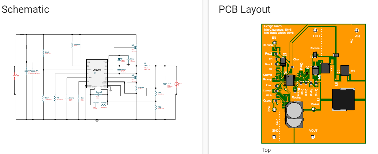
I used WeBench to simulate a buck converter using LM25116MHX/NOPB. The input is 24V and output is 12V, 17A. However when I wanted to export the file to manufacture a PCB, I found that the components in the schematic and board file are different. For e.g. in the picture attached, there are 3 diodes (D1, D2, D3) in the board file whereas only 1 (D1) in the schematic. Please tell me how to proceed.