This thread has been locked.

If you have a related question, please click the "Ask a related question" button in the top right corner. The newly created question will be automatically linked to this question.

TPS2121: Using this part as dual channel load switch

Part Number: TPS2121
Other Parts Discussed in Thread: TPS2120, TPS22810

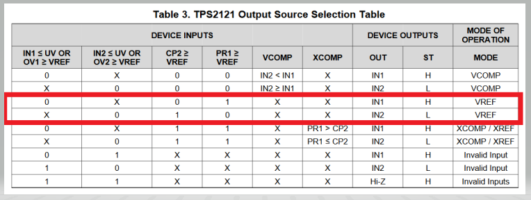
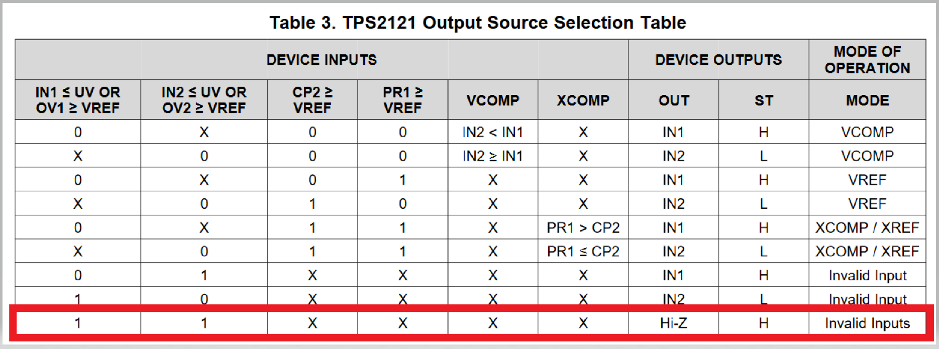
Hello, I have an application whereby we have 12V & 15V supplies, and I want to be able to select one or the other using a couple outputs of an MSP430. How do I do this with the TPS2121? I would prefer the TPS2121 instead of the TPS2120 because it is available in the QFN package. I don't need any over-voltage or under-voltage protection. I saw Figure 20 in the datasheet on how to use an MCU to switch supplies but how do I turn the individual outputs on/off?

How do I connect the PR1, CP2, OV1, OV2 pins for this application?

Thanks,

Derek

  • Hi Derek,

    Thank you for reaching out to the E2E forum!

    In order to be able to control the TPS2121 with signals coming from an MCU I would suggest using the VREF mode of the device. In order to operate in the VREF mode you would have to connect your MCU signals to PR1 and CP2. In this mode the TPS2121 will pick IN1 to be the output source when PR1 is pulled higher than Vref = 1.06V, AND CP2 is pulled low (0V). IN2 can be chosen to be the output source if the opposite happens, CP2 is pulled higher than Vref = 1.06V, and PR1 is pulled low (0V). If you don't need over voltage protection then you can just ground OV pins. Attached will be a table to show the mode of operation you will need to work in for this configuration. 1 - True; 0 - False; X - Don't care

    Let me know if you have any questions!

    Best regards,

    Andy Robles

  • Thanks, this is very helpful.

    For CP2 and PR1, should they both be connected to the 3.3V output pin of the MCU, or should one of them go through a voltage divider so it's a little less (but still above VREF 1.06Vtyp)? 

    Which input will be selected if both CP2 and PR1 are high (3.3V)?

    The application is a two-input, one-output power mux. Inputs are 12V & 15V, max current is 2.5A. Is the TPS2121 the best way to implement this, or should I just use two traditional load switches? I was worried about reverse current; if the 15V switch is on and the 12V switch is off then reverse current could occur through the FET's body diode.

  • Hi Derek,

    If both the PR1 and CP2 voltages are above Vref you will be working in the XCOMP/XREF mode of the device. In this mode it will out IN1 if PR1>CP2, and will output IN2 if PR1<CP2. In order to make it work with the MCU, like you initially stated, you have to send a logic 1 to PR1 AND a logic 0 to CP2 so that IN1 becomes the output source. BY doing the opposite and setting a logic 0 on PR1 and  logic 1 on CP2 you will be setting IN2 to be the output source.

    PR1 CP2 Output
    1 0 IN1
    0 1

    IN2

    Let me know if you have any questions.

    Regards,

    Andy Robles

  • Hello, how do I disable both outputs? Will setting PR1 = 1 and CP2 = 1 turn off the outputs? Or do I need to let OV1 & OV2 rise above Vref?

    Thanks,

    Derek

  • Hi Derek,

    The TPS2121 is a power muxing device designed to have an output chosen between 2 sources. There is an option that will output a high impedance acquired by putting OV1 and OV2 above Vref.

    This is not something that I usually see in designs, but could be a possibility I would need to look into.

    Another option I know would work would be to introduce a load switch, like the TPS22810, to your design at the output of the TPS2121. You can send the output of the TPS2121 to the input of the load switch, TPS22810, and enable this channel with the use of a signal from the MCU throught the enable pin of the load switch.

    Is there a preferred method you would like to go for?

    Let me know if you have any questions.

    Best regards,

    Andy Robles

  • Hello,

       The original design had two load switches but these needed to be paired with Diodes because the load switch (like most) did not have reverse bias protection. That makes things more inefficient.

    Instead of controlling CP2 & PR1 can I just hardwire them somehow and control OV1 & OV2? That should give me the ability to select IN1, IN2, or neither, right?

    The application is super simple: I need a way to switch between a 12V supply or a 15V supply, or neither. Current is 2A but I'd like a 3A or more part if possible. I could use two load switches but haven't been able to find one that supports this voltage & current, and reverse protection. 

    Thanks,

    Derek

  • Hi Derek,

    Although this is not a typical application of the TPS2121 you could connect MCU signals to the OV1 and OV2 pins. This will allow you to operate the device in the modes described by the last three rows of the truth table.

    By doing this you will be disabling the over voltage protection feature of the device since you will be using the OV pins to disable and enable the output. If this is not a concern then the device should operate like you intend it to.

    Feel free to open a new thread or continue commenting on this one if you run into any problems.

    Best regards,

    Andy Robles