This thread has been locked.

If you have a related question, please click the "Ask a related question" button in the top right corner. The newly created question will be automatically linked to this question.

TPS63061: TPS63061 outputs 0.5V - fails upon switching the input ON/OFF a few times

Part Number: TPS63061
Other Parts Discussed in Thread: TPS63060, TPS63070, , TPS62143

Hi!

I used TPS63061 in my board to give 5V fixed output. Input is from a Li-ion battery rated at 11.1V. At lab, I test using a DC adapter with output 13.3V.

The 5V output from TPS63061 goes to TPS79633 and the 3.3V from it powers the rest of my board's circuitry including a microcontroller.

So, my input to the TPS63061 is 13.3V. It worked fine and I reprogrammed the microcontroller on board a few times.

I have a Power ON LED driven by 3.3V to indicate the board status.

Suddenly, when I turned OFF the DC adapter and turned it ON later, the Power ON LED on my board blinks for a sec and then goes OFF.

Then, the adapter voltage is 13.3V at the input of TPS63061 and the output from TPS63061 is around 0.5V. As a result, the rest of the circuitry is OFF.

There is no short between GND and 5V as well as GND and 3.3V. Also, there is no short between VIN-GND, VOUT-GND, L1 -GND and L2-GND.

I have an option to bypass TPS63061 in my board and provide the 5V externally. When I power the board with 5V externally, the board works fine and the current drawn is around 45 mA.

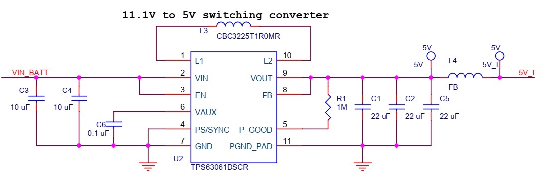
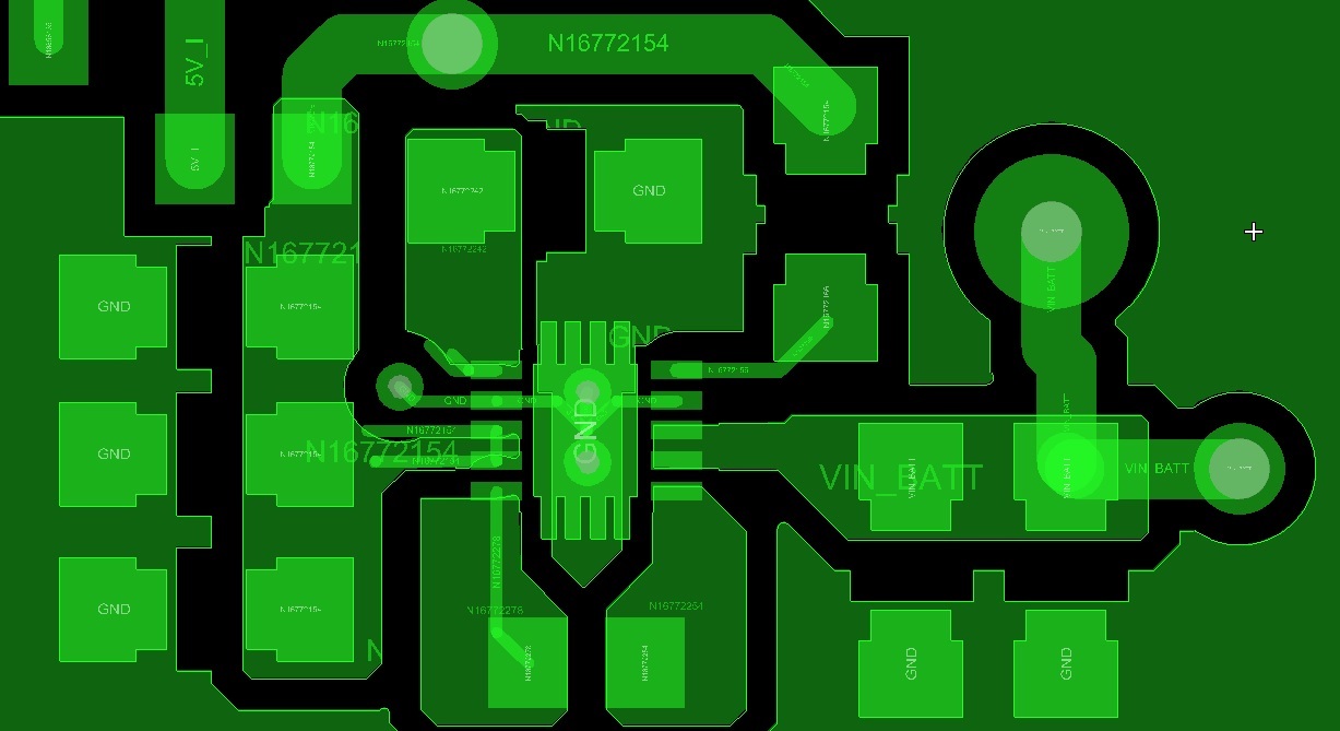
The schematic and the layout of the regulator portion of the board is as given below.

I hereby request for the experts in the concerned domain to help me resolve the issue.

Best Regards,

Raghavan

  • Hi Raghavan,

    The maximum recommended input voltage for the TPS63060 is 12 V. Higher voltage can damage the part. If you have a 3S Li-ion battery than the input voltage can reach more than 13 V. In that case the TPS63070 should be used. 

    As for the schematic and the layout, I have a few remarks:

    1. More GND vias close to GND ends of the input/output capacitors (C1-5) and close to GND pad of the TPS63060 are needed. Please take a look at the recommended layout in the datasheet or the layout of our TPS63060 EVM.
    2. Avoid using vias under the device. If the vias are not plugged, they can suck in the solder, leaving the powerpad not soldered to the board. Please check again the recommended PCB layout. 
    3. The inductor seems to be small, you should check if you are far enough from saturation. What is your maximum load current?
    4. If you are not using PG pin in your design, you can omit R1, and leave PG pin floating or connect it to GND.

    But again, if the input voltage is close to or above 12 V, you should switch to the TPS63070.

    Best regards,
    Milos

  • Hi Milos,

    Firstly, thanks for ur elaborate response.

    As the absolute maximum rating for VIN was given as 17V in the datasheet, I thought it would be safe to apply 13.3V.

    What could be reason behind the blink and miss behavior of power during startup is not clear to me!

    Just 1.3V above the recommended voltage would kill the regulator?

    Reg. the inductor, yes it appears smaller than the recommended one. But, the max rated current through this is 2A. Max load current expected for my board is 1A. Hence, I went ahead with this inductor.

    Reg. layout, I can't make any change in the current board. I will make the necessary changes in the next version. But, with the current layout, will the regulator not function properly? 

    Reg. PG pin, I just followed the circuit as given in the datasheet. Since ur point about PG was not mentioned anywhere, I did not implement it. However, I noted ur point now.

    I would switch over to TPS63070 for my next board.

    Apart from the above, can u pl. confirm if my regulator is permanently damaged?

    What could have killed it? Is there anything that can be done now to bring it back to working condition?

  • Hi Raghavan,

    Please refer to the footnote below the absolute maximum ratings table:


    Therefore, these are only stress ratings. The device is not supposed to operate continuously outside the recommended operating conditions. In your case, it did survive for some time, but eventually it failed. I assume the internal ESD (overvoltage) structure turned on under high input voltage. This protection is not supposed to operate continuously, and likely got damaged leaving the device without a protection, which then caused further damage. I'm afraid the device is permanently damaged. At these voltages the TPS63070 should really be used. 

    For output current of 1 A, that inductor should be fine, but expect a few percent lower efficiency due to larger DC resistance.

    The layout is very important for switching regulators. In your case I wouldn't say it would cause failure under normal conditions, but weak GND routing can cause switching overshoots that can cause EMI issues. And also reliability issues if you are pushing the part close to its limits. Here are some application notes on how to do a good PCB layout when using switching converters:
    http://www.ti.com/lit/an/slva773/slva773.pdf
    http://www.ti.com/lit/an/slyt614/slyt614.pdf 

    The PG pin is an open drain output. In general this type of output can be left floating if not used. We will add that remark in the next revision of the datasheet. 

    May I ask why do you use a buck-boost instead of a buck converter? Is your input only for a 3S Li-ion battery?

    Best regards,
    Milos


  • Hi Milos,

    Thanks again for ur elaborate response.

    It is now clear to me that the TPS63061 should not be operated beyond recommended voltage of 12V and if operated leads to permanent damage.

    This PCB was powered with 12V DC power supply and operated in that condition continuously for around 6 hrs. No issue was found during this process. However, once I used 13.3V DC from adapter as mentioned earlier, its output dropped to 0.5V.

    Yes, I understand that layout is very important for switching regulators and improper layout of the regulator contributed to the damage here. 

    Thanks for sending the notes on layout for switching regulators.

    Reg. my application, I use a 3S2P Li-ion battery, that has max. voltage around 12.6V to 13.5V after full charge and around 7.5V after full discharge. 

    I need to convert the output from this battery to 5V (fixed and stable) to power some on-board circuitry. This 5V would then be converted to 3.3V for the operation of microcontroller and other onboard circuitry.

    Max. current expected is around 1A. In practice, it would be even less than 1A.

    So, shall I go ahead and choose TPS630701 (5V fixed output version) or is there any other regulator suited for this requirement? Pl. suggest.

    Best Regards,

    Raghavan

    Edit: I found one buck regulator TPS62143 which is close to my requirement. What do u reckon?

  • Hi Raghavan,

    The TPS63070 would make sense if you want to power your circuit from either a 3S Li-ion battery or a 5-V USB, for example. But if the input voltage is always higher than the output voltage, then I would use a buck converter. For the same voltage/current specifications, they have lower cost and slightly higher efficiency. 

    The TPS62143 looks good, but I suggest you open a new thread and experts for buck converters will advise you.

    Best regards,
    Milos


  • I am going ahead with the mentioned scheme. TPS62143 with TPS79633.

    Thank u.