


Hi,
I’ve noticed some differences in the choice of Gauge Ground vs Charger Ground between the “TI Drone BMS Reference Design” http://www.ti.com/tool/TIDA-00982 and the BQ40z50-R2 Datasheet (and its TI evaluation board) and I’d like to understand why.
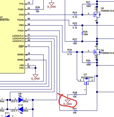
Q7 in Drone BMS goes to Gauge GND:
but in BQ40z50-R2 datasheet, the same mosfet (Q4) goes to Charger GND:

From BQ40z50-R2 datasheet:
"Q4 is provided to protect the discharge FET (Q3) in the event of a
reverse-connected charge ".
Isn't this a medium-current path that should be separated from the gauge circuit (event if, given the suggested mosfet, we're talking max 300mA)?
Same story for the ESD protection devices for SMBus: on the drone BMS schematic, they go to Gauge GND, but on the BQ40z50-R2 datasheet, they go to Charger GND.
Could you please explain me why this difference?
Thanks
Sincerely
