Other Parts Discussed in Thread: TIDA-01573, LMG1025-Q1
Hi TI experts,
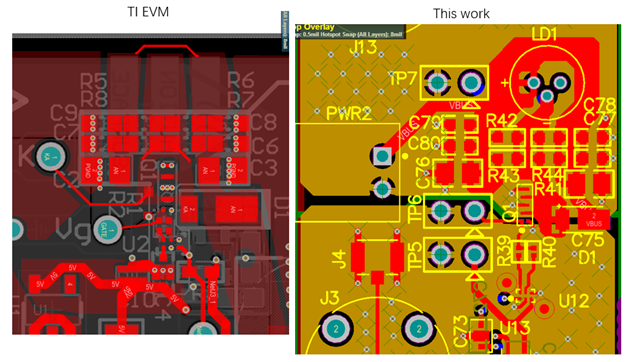
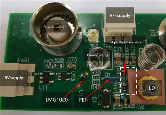
I have built a pulsed laser-driver board following LMG1020EVM. I have put parts as close as possible to reduce parasitics. In addition, layout is very similar to EVM, as shown below.
By tuning pulse width of input signal, I can get approximately 1 ns pulse at AND gate output and LMG1020 output (Vgs signal for subsequent FET), as shown below. In addition, pulse width of AND gate/LMG1020 is proportional to that of input signal. The peak amplitude of current pulse equals to VH divided by 1 Ohm (equivalent resistance of the 4 paralleled resistor).
Afterwards, I replaced the dummy resistors with a pulsed laser diode and performed measurement. The output of AND gate and LMG1020 is the same as before. However, the amplitude of current pulse is only 2 A at 20V high voltage, which is abnormal since the series resistance of a laser diode should be less than 1 Ohm, we should have current pulse higher than 20 A (20V divided by series resistance of LD) instead of 2 A. Why dramatically reduced amplitude of current pulse when FET is loaded by laser diode?
I hypothesized that the parasitic inductance of wire and LD package blocked capacitor discharge. Therefore, I increased the pulse width of input signal. As shown below, the amplitude of current pulse is still very low even at steady state. In addition, we can see a very fast rising edge at the beginning of the waveform and a slow tail until stead state. Why such low amplitude current pulse and why two distinct rising edge?


