This thread has been locked.

If you have a related question, please click the "Ask a related question" button in the top right corner. The newly created question will be automatically linked to this question.

TPS61050: Calculation of Bulk Capacitor to mitigate the effect of inrush current

Part Number: TPS61050
Other Parts Discussed in Thread: LM36010, TPS630242, TPS63802

Hi Team,

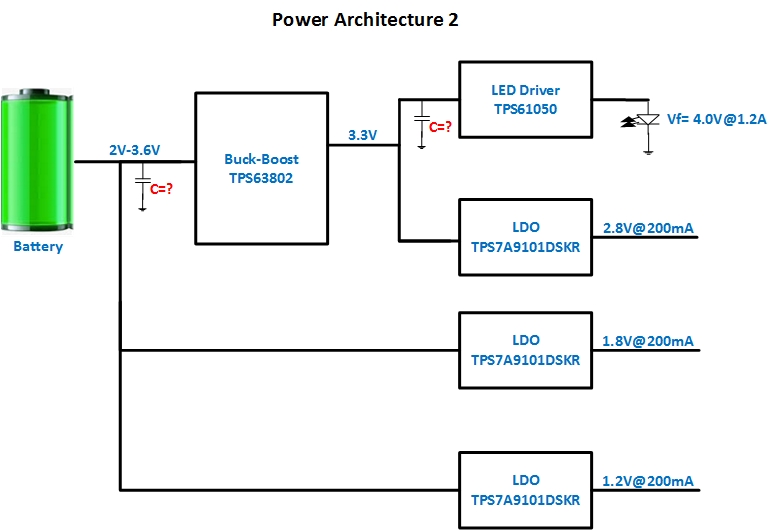
We are designing a camera. In the same we are using flash LED also, and the operating temperature of DUT is -40°C to +85°C. We have worked on two different types of power architecture which are shown below-

We have following doubts-

1) Which Architecture will be more suitable for our design?

2) Flash LED will be turned on for the max time of 250ms. When Flash LED will be turned on it will demand a high inrush current. To provide the same we are planning to provide a bulk capacitor. Please let us know how to calculate the same.

3) In Power Architecture 1 do we need to use inductor at Flash LED driver (TPS61050) since the max forward voltage of LED is 4.0V and the input voltage is 4.2V?  So, there is no need to boost the output voltage.

4) What will be the best position of the bulk capacitor to mitigate the effect of inrush at the time of turning on the flash LED ( Near Flash driver IC or near Boost/Buck-boos)?

5) Please suggest if you have a better part (boost, buck-boost and LDO) which is more suitable for our design.

  • Hi Kumar,

        For this application, I would suggest using our LM36010 which can work under Pass mode or LDO mode, so don't need to consider more about the power rail.

    BR

    Sean

  • Hi Sean,

    Thanks for the suggestion but, due to design limitations we can not use BGA package. If you can recommend any other flash driver IC in other packages (QFN or SON etc), please suggest us.

    Also, we would like to get comments on other points which we have asked.

  • Hi Sir,

        1. I would prefer power architecture 2. since for power architecture 1, 4.2V power supply maybe not enough to driver since there is a headroom voltage;

        2. For the bulk capacitor, that depends on the transient response-ability of the buck-boost device and you can simply use C*deltaV=I*deltaT

    BR

    Sean

  • Hi Sean,

    Ok, we will go with 2nd power architecture.

    For bulk capacitor calculation- We are trying to use the same formula which you have suggested (C*deltaV=I*deltaT).

    Let's assume that we don't want deltaV more than 0.2V and the flash LED current is 1.2A.

    I have also checked the load response of the buck-boost (TPS630242) and as per datasheet, the maximum change is output voltage is 0.2V with a step change of 1.5A of load current.

    The recover time of output is nearly 100us.

    So, should I take deltaT as 100us and I= 1.2A?

    Also, as per our understanding, the bulk capacitor should be placed near the flash driver IC. Please let us know whether this is correct or we need to place the bulk capacitor somewhere else.

  • Hi Sean,

    There is a typo in the above reply which is we are using TPS63802 instead of TPS630242. Please suggest the deltaT and value of inrush current considering TPS63802.

  • Hi Aditya,

        For bulk cap, yes, the T is 100us, for the I since for Vn=3.3V and Vout=4V and Iout=1.2A, the average input current should use Iin_avg=4*1.2/3.3=1.45A.

        So for the deltaV I think it should be small than (3.3V-2.4V)=0.9V since 2.4V will lead to UVLO of TPS61050. 

        So now you can use 1.45A*100us=C*0.9V to calculate the capacitance of Cbulk. Add some margin is better.

        Yes, The bulk cap should be close to the TPS61050 as near as possible.

    BR

    Sean