This thread has been locked.

If you have a related question, please click the "Ask a related question" button in the top right corner. The newly created question will be automatically linked to this question.

LMR14050-Q1: 5V power supply with LMR14050 doesn't work - PART 2

Part Number: LMR14050-Q1
Other Parts Discussed in Thread: LMR14050

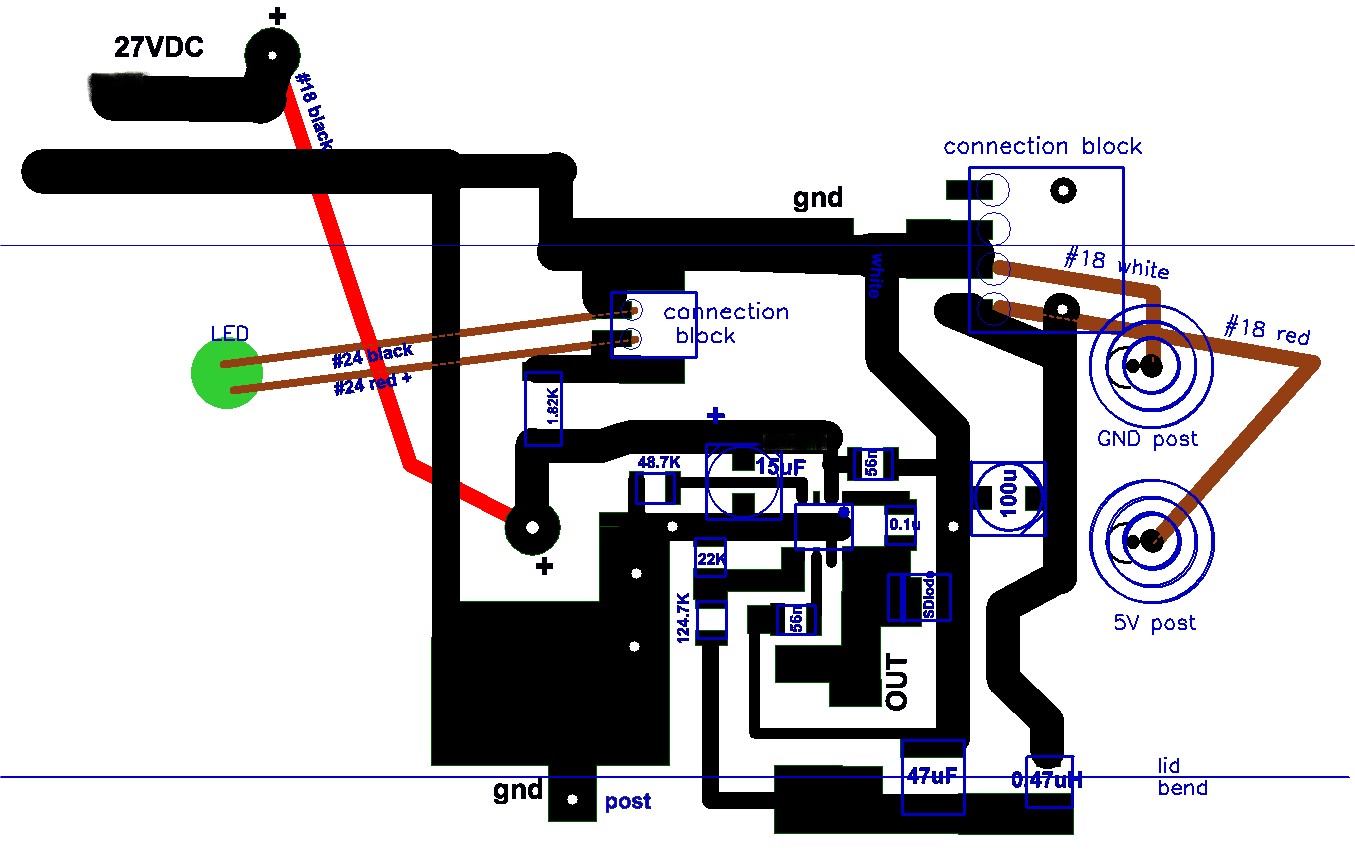
This question is a rerun.  My original 5V power supply didn't work and I questioned why here on E2E.  I concluded I had zapped the LMR14050 and replaced it with a new one.  The new one still doesn't work but with different symptoms.  The schematic is repeated below:

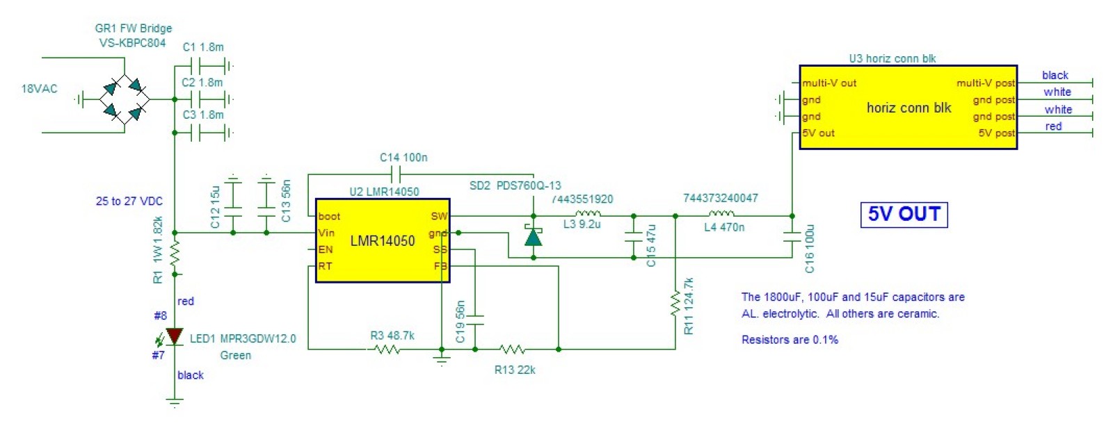
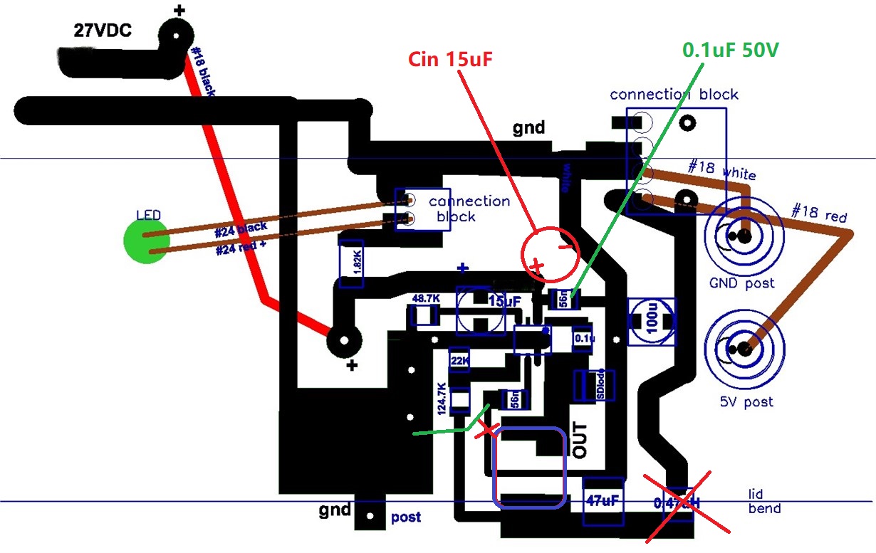
VIN = 26.79V;  VOUT = 0.0V;  VEN on the floating EN pin = 2.5V;  VFT on the freq/sync pin = 9.2mV;  VFB on the Feed Back pin = 0.0V.  VEN is above the 1.2V threshold and seems good.  I don't know what to expect of VFT though I get 2.0V on my working sister multivolt power supply; and 0.0092V seems wrong.  VFB should be 0.75V and is clearly wrong here.  One thought:  when first constructed I inadvertently did not get either the BOOT pin soldered to the 0.1uF capacitor, or the RT pin to the RT resistor.  The datasheet cautions to not tie the RT pin to ground or to let it float.  I did the latter and wonder if that might have destroyed the LMR14050.  Clearly the unconnected boot capacitor would have made it not work but doesn't seem that it would burn out the chip.  Any thoughts?

  • HI

    you can use the attached. I see you connect the wire with cross connection. pls use T connection so that you can avoid some net not connect correctly.

    and pls use small softstart cap , you need wait long time for Vo build up.

    Thanks

    LMR14050 Hands On.TSC

  • Hi Rod,

    Can you upload the PCB layout for checking?

    Pls disconnect the load device and re-test the LMR14050 circuit.

    RT/SYNC pin voltage should be around 0.5V and can't be shorted to ground, float RT pin will not damage the chip.

    B R

    Andy

  • Thanks, Andy,

    FYI the attached layout image shows the 5V half of the two output power supply.  The other half is a switchable 3V, 9V, 12V, and 15V output with a LMR14050 and works as designed.  The layout image does not show the AC input and rectification. There is 5400uF bulk filter capacitance in the rectified input.   I have not yet attached a load to any of the power supply.  I cannot see anything that causes the 5V circuit to not output 5V except for possibly in some way I zapped or fried the chip. 

    ps   I just noticed the 9.2uH inductor between the SW pin and the Output got lost in the image.

  • Thanks, Daniel,

    The output connection block simply allows wire connection from the circuit output to the chassis mounted terminal post.  I actually have two LMR14050 power supplies, a 5V, and a switchable 3V, 9V, 12V, and 15V (which works O.K.)  If I mix them up all that happens is the outputs just go to the wrong post.

    I calculate the t-SS to be 14msec with my 56nF soft start capacitor, and I don't think that is my problem.  I can leave it powered ON for a couple of minuts and still get 0.0 volts output.  I used 56nF simply because I had a bunch of them.

    I notice your hands-on schematic (and the datasheet) has the EN pin connected to VIN even though the datasheet says floating the EN pin should keep it on.  I measure 2.5V on my floating EN pin which should be O.K.  But might connecting EN to VIN work??

  • Hi Rod,

    Pls make below changes and test if circuit works:

    1. Move Cin 15uF 

    2. change Cin-hf 56nF to 0.1uF 50V

    3. Cut Css ground trace, connect to left ground plane by jump wire 

    4. open output 0.47uH

  • Thanks, Andy,  I have some questions:

    I understand that the distance of the input capacitors from the input pin is important, but wouldn't that affect the ripple and output noise as opposed to shutting the regulator off completely?  Is there excessive ringing oscillations that would cause my problem?  The 15uF is an electrolytic specifically to add damping.  (I have been told by reliable sources that the larger input capacitor should be electrolytic, AND also that the larger capacitor should be ceramic, though all say the hf capacitor should be ceramic.).

    For the hf input capacitor, is there a significant difference between 56NF and 100nF?

    I don't understand the soft start capacitor change.  I didn't think it to be critical.  Is it possible that the larger than usual capacitor with the longer thin ground connection somehow results in slow start times in the minutes???

    I don't get the 0.47uH inductor removal.  I have a two-stage output LC filter because I was told that is much better for high frequency ringing and noise.  The 0.47 inductor is in the direct output path;  if I remove it there is just the single stage LC output filter and I would have to jumper the opening to access VOUT..  What am I missing here?

    BTW there was a question about where to attach the FB resistor in a two-stage LC output filter.  I found two knowledgeable answers.  One said definitely after the second stage.  The other said definitely NOT after the second stage.  After a trial I went with the latter -- between the 1st and 2nd stages.

    I sincerely appreciate your assistance.

  • Hi Rod,

    On your PCb layout, Cin 15uF will make ground quite noisy for RT and FB, so it should be placed as I suggested, it's not for ripple

    Cin_hf=56nF is OK to use, but it should be 50V or higher rated in 0603 size.

    Css=56nF is Ok to use.

    Remove 0.47uH is to isolated the load which may cause unstable working while debug the converter circuit,  

    Sense output after 1st stage is much easy for circuit design, LMR14050 prefer to sense at 1st stage because it's compensated internally.

    I mentioned you use 3x1.8mF input cap, can you try it with only one 1.8mF cap for debugging? did you ever measure input voltage startup waveform? how about the ramp up slew rate?

    B R

    Andy

  • Hi Andy,

    I can't move the 15uF input capacitor because of a space problem -- it won't  fit under the rotary switch mounted on the cover..

    I don't have waveforms of the input because I don't yet have a scope.  But it is hard to imagine that is causing my problem because the sister multi-volt power supply uses the same source and works fine.

    I can't get past the 0.0 voltage on the FB pin.  So I will try to replace the LMR14050 and say a prayer!

    Thanks so much for your help.  I'll let you know how it turns out.