Hello, I will describe the problem here:
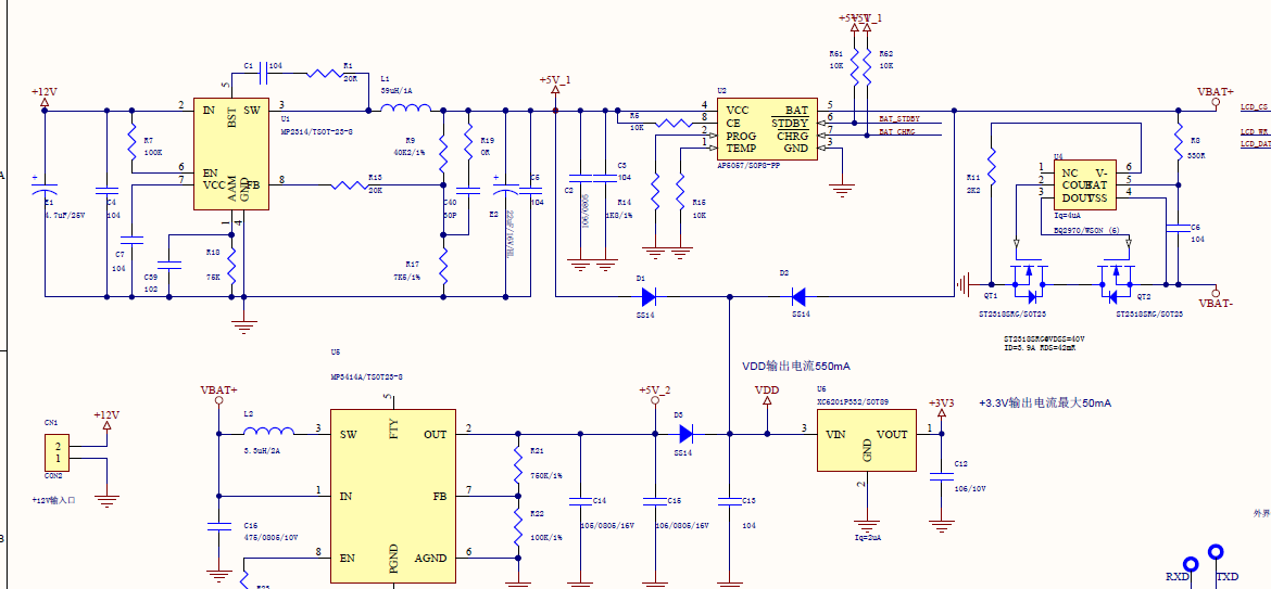
1. Without access to the + 12 V, separate by one between VBAT + VBAT - batteries, battery voltage of 3.8 V, MCU and LCD has connected, buzzer, test to VDD and 3 v3 no voltage, QT1 G and VBAT - between the voltage is 2.8 ~ 3.0 V, the QT2 G and VBAT voltage is less than 0.01 V, the QT2 DS is extremely short circuit, the output is normal, the judgment is QT2 conduction.
2. Under the above test conditions (already connected to the battery), access 12V, output normal, load normal work; Turn off 12V, then the battery can still work normally, and test the voltage between QT2 G pole and VBAT- is 3.8v.
3. According to the data, the conduction resistance of QT1 and QT2 is detected by the chip. It is recommended that a single conduction resistance is 7.5mr. Moreover, after I short-circuit QT2, the voltage between QT1 and QT2 is only 2mV, which is the same as the voltage after testing QT2 and QT1.
Could you please tell me that this chip BQ2970 working mechanism is not available on a separate battery?