


Hi,
I'm finishing the schematic design of my board (it is 90% based on the reference EVM).
I have some questions to solve:
1) Can I put the TVSs on each inputs (including the thermistor-in ?)
2) As I understood, the wake-up circuit in the EVM is needed only for development purposes to produce a current flow. I removed from my schema. There is any implication?
3) The precharge current should be the around 10% of the nominal maximum current of charge. So, for my battery pack that has 1.5A I choose 100mA of precharge. Is it correct this approach?
4) In the 6s configuration, where should I put the 4 thermistors on the pack (on the interface of each battery)?
5) For the configurable Pins, if I put the unsed to VSS before the configuration of the board with the new FW, is there a problem of a short circuit if the pin is configured as output and connected to the ground?
6) Can I configure the current on the LED? I have a small LEDs that require 22mA and not the typical 30mA
7) For the Shutdown input, as I understood from the datasheet there is an internal pull-up. So, I don’t put any pull-up network. Is it correct?
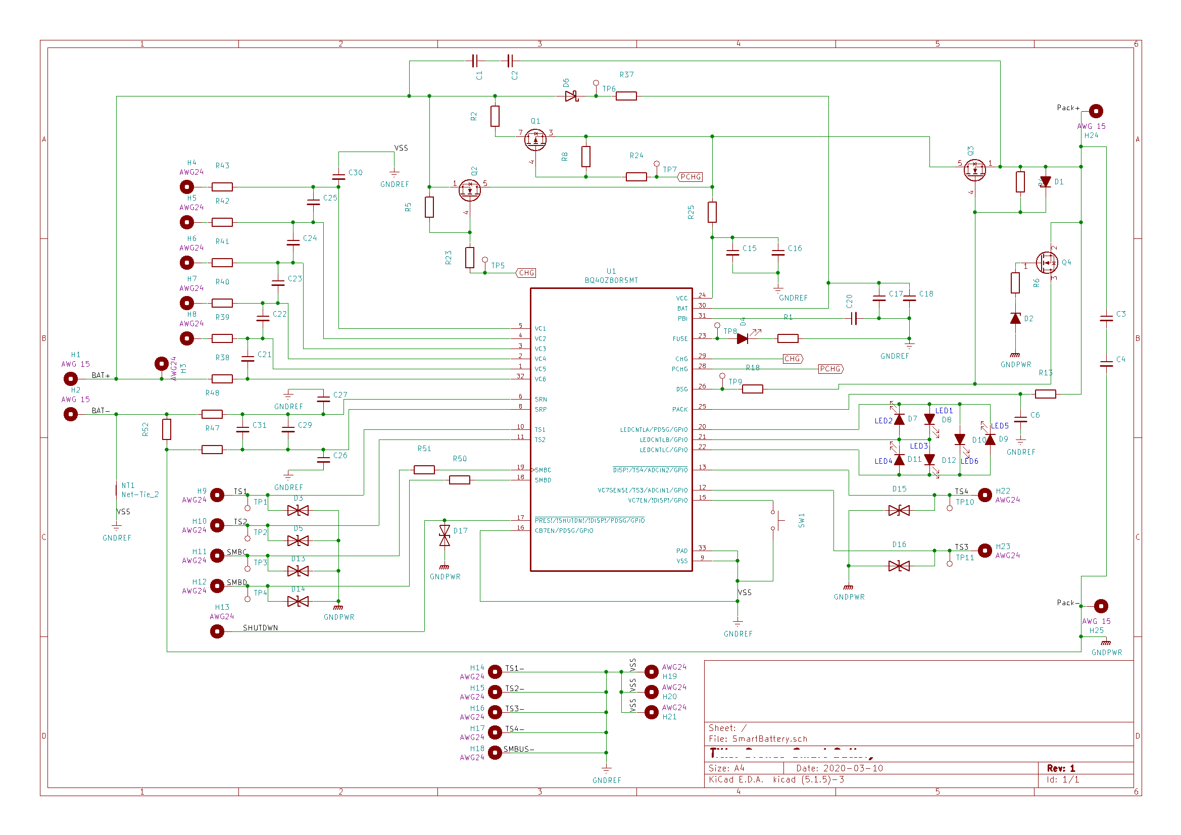
8) Can you provide a general feedback on the following schematic, in case of macroscopic error?
9) The fuse pin, can drive with 8V a Led?
Thanks for your support
 .
.


