Other Parts Discussed in Thread: LMR14020, LMR14050
Hi,
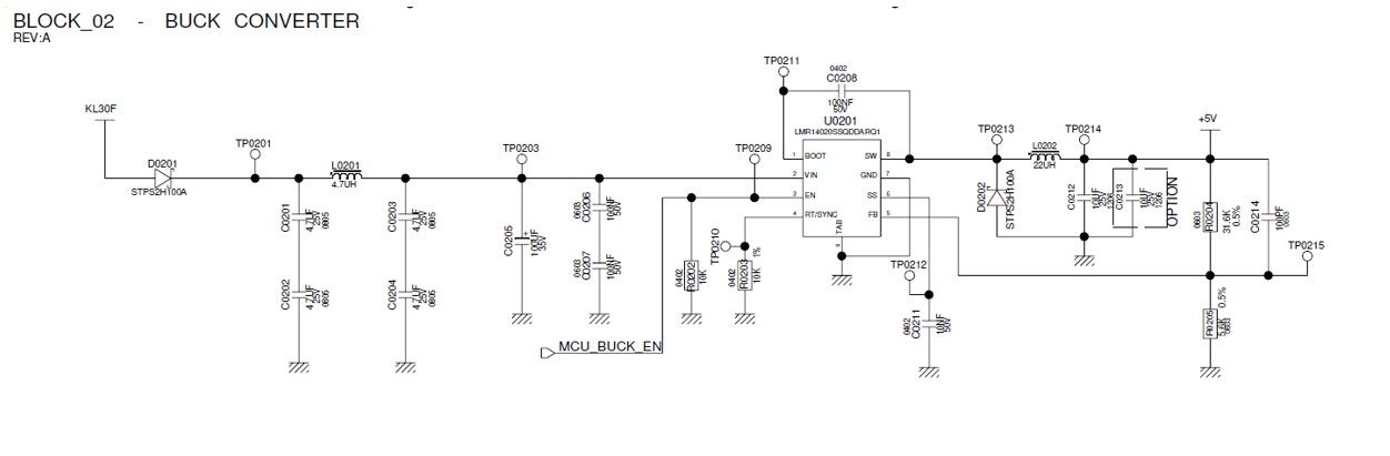
I am using LMR14020 (HSOIC package) Automotive qualified component for one of my Project.The following Inputs are Vin=6V to 16V ; Vout= 5V; Fsw=2.1 MHz. The schematics as shown below
When I apply Input voltage=6V . The voltage across buck input pin is 5.18V for 0.5A Load rate & 5.03V for 1A and also the output voltage is 4.866V (0.5A) & 4.585V (1A). The switching frequency at input voltage = 6V is given below
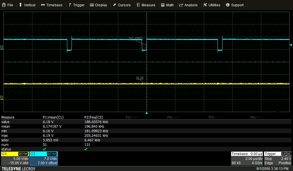
The switching frequency goes to 200 KHz .Instead of 2.1MHz (which is I'm using). Is it the switching frequency really decreases based on the input? Are there is any error due to internal compensation circuit.
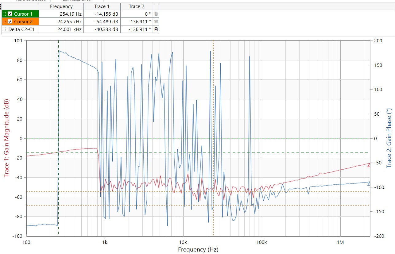
And I also having problem in transient stability at 6V and I also can't get desired frequency (1/20 Fsw< Fc<1/10 Fsw). The bode plot is attached below. Kindly clarify whether it operates under Input voltage =6V. If yes what about its switching frequency and its transient stability?