This thread has been locked.

If you have a related question, please click the "Ask a related question" button in the top right corner. The newly created question will be automatically linked to this question.

About DCAP 2 Operation and DCAP 3


Hello all,

I'm looking the DCAP 2 topology, and could find this.

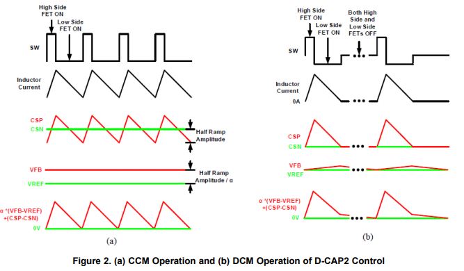
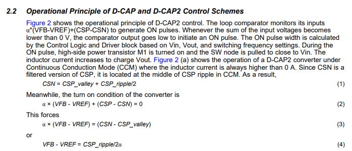
I know that DCAP 2 has internal ripple injection circuit for the low ESR output capacitor, and "Emulated Ramp Generation" looks like internal ripple injection circuit on the the below picture. 

Usually the ripple injection circuit is composed with Rr, Cr, and Cac, but there are CSP, CSN. I read all the document, but I do not understand what these are, how they work and the relationship between Vref, Vfb, CSP, CSN on here.

Could you please explain more detail?

http://www.ti.com/lit/an/slva762a/slva762a.pdf

Also, I do not understand the relationship between CSN_NEW, CSP, Vref, Vfb about DCAP 3 on this document.

Could you please explain, also?

Thank you 

  • Hi

    You can simply think the CSP/CSN is same with external ripple injection circuit with RCC.

    And for Dcap3, it is added some sample and hold circuit to improve load regulations based on Dcap2.

    Yuchang

  • Yuchang,

    Can you explain more about the CSP and CSN more what it is?

    I know that sample and hold circuit make the offset voltage between Vref and Vfb 0.

    I want to know the principle to remove offset voltage.

    Thank you

  • Gary,

    Sorry for late reply. As I said before CSP/CSN are mainly used for ripple injection to meet lower ESR output caps application, CSP is the first filter stage from switching node and CSN is the second stage filter from switching node. different IC may have different design with this, but  actually the S&H circuit in real design is mostly used integrator to cancel the half ripple, then can help to improve load regulation.

    For system application, you know, actually CSP/CSN is inner design, not related to external component design. so you may just get Dcap3 has good load regulation with S&H integrated.

    Yuchang

  •  

    The labels CSP and CSN refer to "Current Sense Positive" and "Current Sense Negative"

    The R-C across the inductor can also be used to sense the inductor current using the DCR of the inductor.  If the R-C time-constant is matched to the L - DCR time constant such that RC = L/DCR, the voltage across the capacitor will be equal to the current through the inductor times the DCR of the inductor.

    As  notes, this is just another label for the nodes in the circuit and does not affect the circuits functionality.  For D-CAP parts, Rc1, Cc1 and Cac are external, for D-CAP2 and D-CAP3 devices, these are internal components with either fixed values, or selectable values.

    Since Constant On-time (COT) Control is a valley regulation scheme, external RCC injection and D-CAP2 impost an offset to the output voltage equal to 1/2 of the amplitude of the injected ramp due to the offset between the average injected value and the valley of the injected value.  D-CAP3 uses an internal Sample and Hold circuit to cancel this offset and improve regulation accuracy.