This thread has been locked.

If you have a related question, please click the "
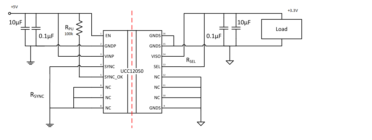
Ask a related question" button in the top right corner. The newly created question will be automatically linked to this question.

UCC12050: UCC12050

Part Number: UCC12050

I bought a UCC12050 and have tested it with the recommended application circuit shown in the attached image. I am inputting 5V and wanting to get as close to 5V as possible, so I shorted SEL to VISO as directed. However, I'm only getting 3.3V. Does the input voltage have to be >5V in order to get 5V output? Is something wrong with the application circuit?

  • Hello Jared,

    Thank you for your interest in the UCC12050 isolated bias supply.

    This device can generate up to 5.4V output with only 4.5V input, so it is not a question of input voltage.

    Since you are getting a regulated 3.3V output, I suspect that the SEL input is inadvertently shorted to GNDS, even though you intended to short it to VISO.
    For example, perhaps you miss-counted the pins and soldered 12 to 13 instead of 13 to 14.  Please double check your pin-count and connection.

    Regards,

    Ulrich

  • Hello Jared,

    Please check you circuit for the following:

    1. Have you set the SYNC_OK pin low since there is no external clock.

    2. once SEL is shorted with VISO: what load is applied at the output when you see 3.3V? Please double check that this pin is not shorted to GND.

    3. Do you see 3.3V even with no load?

    4. What is the voltage across the 10uF input capacitor? 

    Regards,

    Sonal

  • Hi Sonal,

    Thank you for your response. 

    1. Both SYNC_OK and SYNC are connected to ground.

    2. There is no load when I see the 3.3V; I double checked that the pin is not shorted to ground.

    3. Yes

    4. The voltage across the 10uF input capacitor is 5V. Once I set SYNC_OK and SYNC to ground, it outputs 5V occasionally with 5V across the 10uF input capacitor. If I increase the input voltage to 5.5V, it sometimes gives 5V on the output, and sometimes 3.3V.

    Best,

    Jared

  • Hello Jared,

    If the unit intermittently puts out 3.3V and 5V, then that can be a symptom of an intermittent connection.

    I suggest to remove the IC from the board, clean the pads and resolder.  Take care to avoid cold solder-joints and solder balls between pads.

    Regards,

    Ulrich

  • Hi Ulrich,

    Thank you for the suggestion! I was able to get one to work, but when I placed three of them on the PCB I will be using (with no load), I get ~1.5V from each. I tested and retested to make sure that each was wired correctly, and they are. If there was a load, I would assume that would be the issue, but there's not. Any thoughts on that?

    Best,

    Jared

  • Hi Jared,

    I'm glad that you got one working. 

    Now with 3 on one board, you get only ~1.5V which is not any of the normal output levels. If you run only one of each alone, do you get the 5V you expect?

    You mention 3 units, but "If there was a load,..." implies one load, which implies that you may be paralleling 3 converters to get higher current that one unit alone can deliver.  Is that the case? 

    If so, I do not believe that these parts can be paralleled, at least not directly. The datasheet does not prohibit this explicitly, but I suspect that the internal control is not designed to "share" power with another unit. 

    How are you measuring the ~1.5V with a DMM?  It may be more revealing to use an oscilloscope to see if Viso is trying to rise up, then falling again in shutdown/retry attempts with each unit interfering with the other units.

    All of the above is my conjecture, because I don't know what your full circuit looks like.  But if you are trying to parallel, there is a slim possibility that a series resistance on each output might help to decouple each regulator from the other outputs.  If you change the Viso to 5.4V and insert 4.0 ohms in series, then the 100mA output current will drop Viso back down to 5.0V.  But the hope is that the 4ohms on each output may help stabilize the paralleled operation.

    Adjust the series-R value up if your current level is lower. 

    So:
    1. Use a 'scope to view Viso to verify the output.
    2. Run only one unit at a time to verify that each one can work, from no-load to its rated load capability (depopulate the other converter ICs, or isolate their outputs).
    3. Try adding a series resistance in each output to see if it helps them to share, first between only 2, then if successful, between all 3.  
    4. Another idea is to use a Schottky diode in each output instead of the resistor.  The units may not all start-up at the same instant and this would prevent one overloading the other(s) when they are powering up. You may need some common output capacitance. 

    Regards,

    Ulrich

  • Ulrich,

    Thank you for your prompt responses.

    1) I removed one of the isolators and disconnected the other, so that there is only one connected. It is still giving the same voltage (~1.5V).

    2) I apologize for my unclear wording, but the isolators share only the same input (which is rated to supply 2.5A), and their outputs supply isolated loads.

    3) The oscilloscope reading was a constant voltage with not oscillations.

    Attached is a picture of the PCB. Thanks again for your patience and help!

    Regards,

    Jared Curtis

  • Hi Jared,

    Thanks for the photograph.  The resolution is high enough that I was able to zoom in and examine it very closely.

    If I traced it correctly, and if you are using 10-uF SMD tantalum capacitors on each output, then I think C10, C14, C18 and C22 may be installed backwards.  The black case style with white band on one end gives a hint that they may be tantalums. Tantalum cannot withstand high reverse voltage and will pull Viso down due to the limited output current of the UCC12050.

    Please check the polarity of these parts.

    Regards,

    Ulrich

  • Ulrich,

    I switched the capacitors, and it worked perfectly! Thank you so much for your help!

    Best regards,

    Jared Curtis