This thread has been locked.

If you have a related question, please click the "Ask a related question" button in the top right corner. The newly created question will be automatically linked to this question.

BQ24133: charge current abnormal problem at 0C degree

Part Number: BQ24133

Dear expert,

My customer is using BQ24133, but met some problems. They found at 0C degree test (only this temperature point is abnormal), when near to the full charge point, there appeared the charge current transition phenomenon between 0-500mA as below.

The schematic is attached here as well.Copy of 原理图.xlsx

Customer already tried these methods, but didn't work.

1. When charging at 0-45 ° C, TSPin is connected to VREF resistor RT1 to adjust the parameters of GND resistor RT2. The adjustment range of the temperature window has been extended to -5-50 ° C, and it is invalid.
2. For the high and low temperature charging threshold voltages VLTF and VTCO's Full C and Suspended voltage fine-tuning, several combinations of RT1 and RT2 are deduced, and the attempts are invalid;
3. At low temperature, mesure the resistance value of the RTC resistor, cooperate with the adjustment of VLTF and VTCO, and is invalid.

Please kindly share some suggestions. Thanks!

  • Dear Minqi,

    If possible, can you zoom in on the part with the termination error? I suspect that your termination coupled with your choice of sense resistor is triggering termination early. Then after the current is dropped, your battery drops below regulation and charging starts again. This cycle continues on and off and could be a possible explanation for your phenomenon above.

    Also, what do you mean by "these methods?" Are you saying this is what was tried to fix it but didn't work?

    Thanks,

    Mike Emanuel

    Please click "This resolved my issue" button if this post answers your question.

  • Hi Michael,

    Yes you are right, "these methods" is what was tried to fix it but didn't work. Based on previous schematic, customer did adjustments as below:

    1. ACN to ground C101-->NC;

    2. SRN to ground C120-->NC;

    3.Battery cap C114-C117-->NC;

    4. Idpm-->2.5A,Icharge-->2.5A

    Thanks for your suggestion. I asked customer to recapture the termination error at 0C. Please see attached file. These are two boards with same set up at 0C condition.

    Also, we find another odd phenomenon. Customer said the battery volume is 2900mAH, they set charge time to 2 hours, but the test charge time is over 3 hours. The charge time extend happened at room temperature as well. Is it related to the termination error at 0C problem?

    Look forward to your suggestions.

  • Dear Minqi,

    I would not recommend removing the capacitance for the battery nor the SRN and ACN capacitors. I think the problem is associated with the impedance between the battery and the charger. The termination current is set to 10% of the charge current. In this case 250 mA. As an example, say your the impedance between the battery and the charger was 1 ohm. When the pin on the charger reaches regulation of say 8.4 V, the actual battery voltage is 8.15 V. Because the charger thinks it reaches regulation, it turns off the charging current. Now the charging pin settles at 8.15 V from the battery, triggering recharge on and off again as you are seeing above.

    Can you confirm that the impedance of the line is not causing the charger to terminate charge and recharge cyclically?

    Thanks,

    Mike Emanuel

    Please click "This resolved my issue" button if this post answers your question.

  • Hi Mike,

    Thanks for your suggestion. 

    Customer tested the impedance at room temp as below: 

    1. Use LCR Meter to measure the impedance of SRN from IC Pin15 to battery holder J101 Pin3 is 0.2ohm;
    2.Use LCR Meter to measure the impedance of SRP from IC Pin16 to sense resistor R105 is 0.2ohm;
    3. The internal resistance of the battery measured by the battery internal resistance tester is 0.204ohm, and the measured battery voltage is 8.25-8.29V.

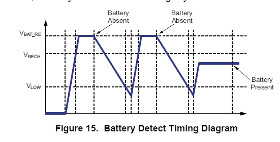
    At present, VBAT_RE is the SRP voltage and VRECH is the SRN voltage. The difference between the two is 0.11-0.15V, it seems that the range is within 200mV, which should not violate the alternate charging.

    However it seems that at 0C, maybe the impedance change and cause the battery voltage lower than 8.2V, triggering recharge? Is this analysis reasonable? 

    So my questions are:

    1. How to change the impedance to leave more margin, so at 0C the recharge won't be triggered either?

    2. Should they redisign the current sensing resistor R105 10mOhm/1%, and use more accurate resistor? What's your suggestion?

    3. They also find the reason of charge time extend is that the input current is 2.5A but the output current is 2A. What may cause the error? The input current sensing resistor R100 20mOhm/1%.

    Thanks a lot for your help!

  • Dear Minqi,

    Can you please check if you are using a protector for the battery? If so, what is the impedance of the protector? This could be additive to the impedance of the line connecting to the battery.

    In addition, I am wondering if the battery being used to test is relaxing more due to age? When the current is removed from the battery, the higher impedance may cause the battery voltage to relax below the recharge threshold. Can you please try with another battery that is newer to confirm this is not the issue?

    Thanks,

    Mike Emanuel

    Please click "This resolved my issue" button if this post answers your question.

  • Dear Minqi,

    For the difference in input and output current, it appears that your input current limit is actually set to 2 A. It appears your VACSET voltage is 0.81V. Following the calculation in the datasheet, the input current limit is 0.81V/20/20mOhm or 2.02 A. If you wish a higher input current, the divider for VACSET needs to be adjusted.

    Thanks,

    Mike Emanuel

    Please click "This resolved my issue" button if this post answers your question.

  • Hi Mike,

    Thanks a lot.

    About 0C charge current transition phenomenon, customer said they did add protector. However, they wonder is this phenomenon popular among other customers due to the Li-on battery performance is not so stable at 0C? If so, they can explain to their end customer and don't need to focus on this problem.

    Look forward to your comments, thanks!

  • Dear Minqi,

    Can you please try to charge this battery at room temperature and report on your findings? Colder temperatures increases the internal resistance of the battery and can further increase the relaxing effect. This would contribute to coming in and out of regulation very readily.

    Thanks,

    Mike Emanuel

    Please click "This resolved my issue" button if this post answers your question.