This thread has been locked.

If you have a related question, please click the "Ask a related question" button in the top right corner. The newly created question will be automatically linked to this question.

UCC28740: Not performing startup operation

Part Number: UCC28740

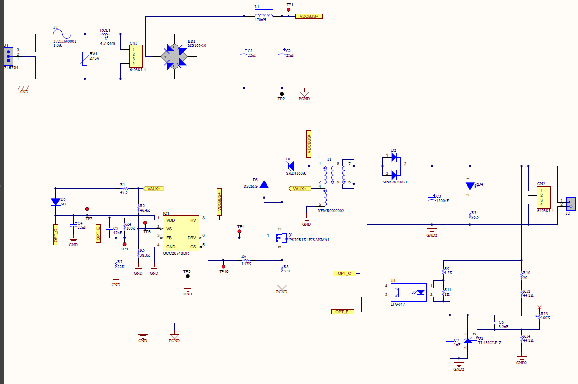
Hello, i have the circuit assembled like the attached image.

testing the PCB assembled the circuit performs the charging of the Cvdd capacitor up to 21v but measuring with the oscilloscope the IC does not sends the 

initial 3 pulses specified in the datasheet.

Do you know what could be wrong?

Thank you.

  • Hello Luis,

    Thank you for your interest in the UCC28740 flyback controller.

    I notice that you have the Auxiliary wind polarity connected backwards.  Please reconnect such that the dot (pin 4) goes to primary GND and the other end (pin 5) goes to VAUX+.  That should help start-up.

    If that does not fully solve the problem, please follow the debug guide procedure here: www.ti.com/.../slua783.pdf

    It is written mostly for PSR-type controllers, but many of the steps apply to the SSR-type controllers, too.

    Regards,

    Ulrich 

  • Thank you Ulrich, that solved the issue.

    Could you help me to undertand how the aux winding helps in the startup operation since it is not energinzed up until the mosfet is drives the primary winding and int his case the mosfet is not driven by de ic yet?

    Thank you

  • Hello Luis,

    The IC must drive the MOSFET at least once in order to get any information from the AUX winding, and that is what has happened.

    The first three pulses are very narrow, just enough to test for input line voltage and any other possible operation issues, and the IC decides what to do based on the test results. In the case of a reversed winding, it may need only one pulse to determine what appears to be an extreme short circuit and shutdown immediately.

     The polarity reversal makes the power stage behave as if it was a forward mode topology, but without an output inductance, so the output capacitance appears as an AC-short and the primary current can rise to huge peaks in nanoseconds limited only by leakage inductance. 

    These test pulses occur at the peak of VDD immediately after it crosses the turn-on threshold (about 21V).  They are easy to miss unless you set up a trigger for them.  The datasheet goes into more detail about each kind of fault condition that is monitored and what the controller's response is to each.

    Regards,

    Ulrich