This thread has been locked.

If you have a related question, please click the "Ask a related question" button in the top right corner. The newly created question will be automatically linked to this question.

UCC28881: Open Fuse when applying 240VAC

Part Number: UCC28881
Other Parts Discussed in Thread: TINA-TI,

Hello,

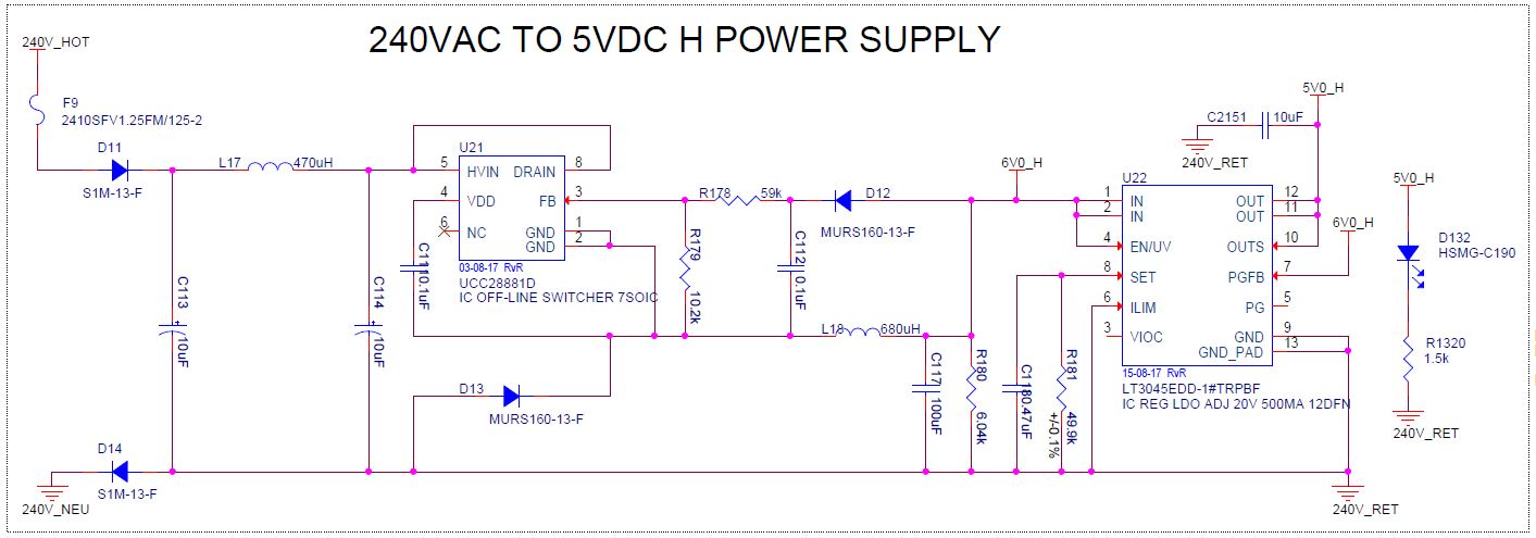
I've developed a PCBA that uses the UCC28881D to regulate (30VAC-240VAC) down to 6VDC. Multiple versions of this hardware have been built and tested.

On the earlier rev (the one we call Rev 0.5), we have a half-bridge rectifier at the input and an input filter that includes two 10uF capacitors. This design has been working fine.

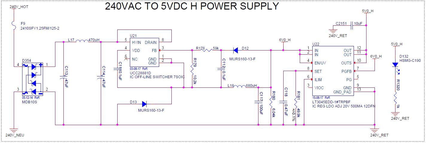
To reduce input ripple coming into the UCC28881D, we created another revision (called Rev 1.1) which uses a full-bridge rectifier and increased the input capacitors to 47uF each. On this revision, we have been blowing fuse F9 (2410SFV1.25FM/125-2) on multiple boards.

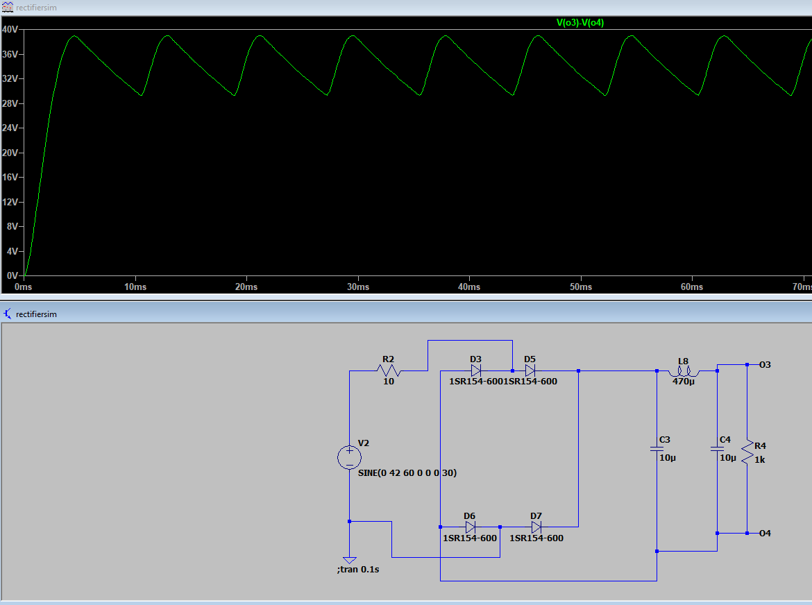
I downloaded the PSpice model of the UCC28881 from TI's website, but I haven't been able to get the simulation working in TINA-TI. When I try to create the macro in TINA, I get the error message "Invalid Device: $CDNENCSTART. Line: #42. $CDNENCSTART". I also tried importing the model into an LTSpice simulation but when I try to run it I get an error message saying that there are too few nodes.

Could you please help me with the following:

  1. Are there any differences you see between Rev 0.5 and Rev 1.1 that would explain why Rev 1.1 fuses blow and Rev 0.5 fuses don't?
  2. Can you please provide a model for the UCC28881D that I can use in my simulation?

Could you please review the circuit diagrams I've attached and let me know if there are any mistakes or if any tweaks are needed

  • Can you change the fuse to slow blow type? It looks after you increase the input capacitance and change to the full bridge rectifier, the power inrush current is much higher comparing your Rev 1.1 to your Rev 0.5.

    Usually the input fuse should be slow blow type as the very fast acting does not seem help make protection to semiconductor devices. So slow blow fuse is actually to break the overload if it lasts too long.

    You can also change C113 to 10uF to have a try on your rev 1.1. But to my understanding the fact acting fuse is likely the reason.

    We do not have another model that can provide to you.   

  • Thanks Hong,

    That is correct. With the caps changed to 47uF each, I'm getting 7A peaks for about 6 msec, enough to open the fast blow fuse that I had in there.

    A slow blow fuse that we had in mind is Bel Fuse's 0697H4000-02 (or the 10Ohm that the webench simulation recommends: AC03000001009JACCS).

    You've recommended to change the caps for 10uF each. My concern is the 30VAC RMS (42V peak) operation. I ran the simulation for the rectifiers and got the following output:


    The ripple's min=29V and max=39V. Section 7.5 of the UC28881's datasheet states a minimum voltage to startup = 30V (MAX). Will the output above be sufficient to meet this requirement (given that we're dipping to 29V)?

    Thanks.


  • I am not recommending you change 47uF to 10uF. I am suggesting to change 47uF to 10uF to if the fuse stop breaking. The critical thing here is to use a correct fuse - I suggest to use slow blow type.

  • We will definitely change the fuse, but I would also like to reduce that peak current if I can (down to 2.2A instead of 7.2A). You suggested a 10uF cap instead of 47uf. If we do so, we'll run into the issue I described above when the input is 30vAC RMS (according to simulation).

    My questions: Is that a problem?

    Thanks.

  • I suggest you to test to find out. Also, you do not have to split the input cap into 47uF and 47uF. The one on the left of DM choke can be smaller and the one on the right can be bigger but total will be similar.

  • Hi Hong,

    You did not answer my question; I need to better understand the spec mentioned in section 7.5 of the UC28881's datasheet (minimum voltage to startup = 30V MAX). Even if it works, I'd like to understand why it's working. The ripple dips below 30V (~27V). Would it work because the switcher has already been kick-started when the Vin>30V? Please clarify.

    Regards,

    Bassam Mansour

  • Based on section 7.5, to guarantee to start, your application needs input voltage not less than 30V at start. After start, the IC will keep operation as long as VDD > VDD(off) = 3.62V typical.