This thread has been locked.

If you have a related question, please click the "Ask a related question" button in the top right corner. The newly created question will be automatically linked to this question.

BQ25606: Use of BQ25606 for low current consumption

Part Number: BQ25606
Other Parts Discussed in Thread: BQ25616

Dear Sir,
I need to develop a portable device powered by a LiPo single cell battery. The system need to charge battery with the correct current depending by the power supply used (5V and 500mA, 1A, 2A depending by the adapters). When the adapter is disconneted, the battery needs to supply the system only if the switch is on, otherwise the current consumpion must be 0A. When the adapter is connected the system must be powered by Vbus indipendently if the switch is on or off.

Now my questions:
I thought to use the BQ25606 as battery charger.
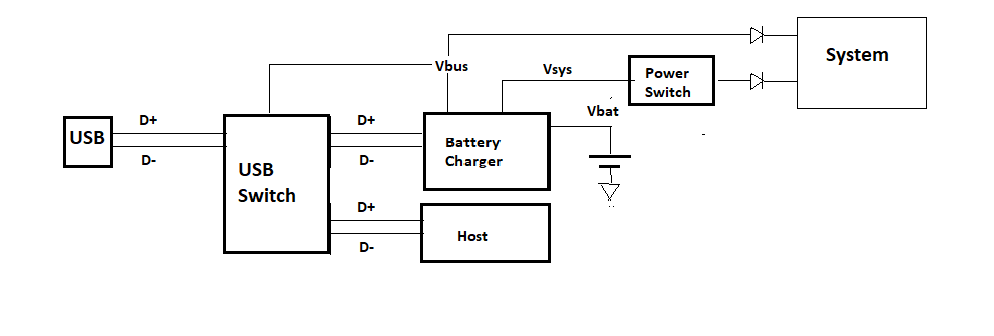
1. I read in the forum that it can recognize the adapter by USB sygnals, but if the USB is used by the host it's needed a USB switch. It's correct?
2. The battery charger can supply a regulater output voltage by SW or PMID. What is the right way to provide the power supply to the system, by using SW or PMID?
3. Whe the USB is not connected and the power switch is OFF (System non connected) what is the current asorbed by the BQ25606?
4. The scheme I thought is correct or there is a best way to connect the part I need?
Thank you.
Best Regards.
Giuseppe

  • Giuseppe,

    Are you looking for stand-alone charger without I2C communication? Before getting to your questions, if you are looking for low current consumption stand-alone chargers, it is better to use BQ25616/J.

    Thanks,

    Ning. 

  • Dear Ning,

    thank you for reply. Yes, the BQ25616 can be suitable for my application.

    Please, can you reply to my other questions related to the use of this battery charger?

    1. I read in the forum that it can recognize the adapter by USB sygnals, but if the USB is used by the host it's needed a USB switch. It's correct?
    2. The battery charger can supply a regulater output voltage by SW or PMID. What is the right way to provide the power supply to the system, by using SW or PMID?
    3. Whe the USB is not connected and the power switch is OFF (System non connected) what is the current asorbed by the BQ25616? It's 9.5uA?
    4. The scheme I thought is correct or there is a best way to connect the part I need?

    Regards

    Giuseppe

  • Giuseppe,

    1. D+/D- pins are used for USB input current limit detection when VBUS power is plugged in. During the charger input current limit detection process, the host must be able to HIZ D+/D- pins so that D+/D- pins are driven by the charger. If the host is unable to HIZ D+/D- pins, a USB switch is needed to isolate the host and the charger.

    2. In charging mode, VBUS is the adaptor input. The internal n-channel reverse block MOSFET (RBFET) is connected between VBUS and PMID. PMID is basically VBUS with current limit (IINDPM). SYS is the system load output. Please follow BQ25616 Application Diagram on the d/s and EVM User's guide for your own design.

    3. When only BAT=4.5V and BATFET is on, the battery quiescent current is typical 9.5uA.

    4. Ok.

    Thanks,

    Ning.